26
3. System Configuration Example
3-1. Basic Configuration
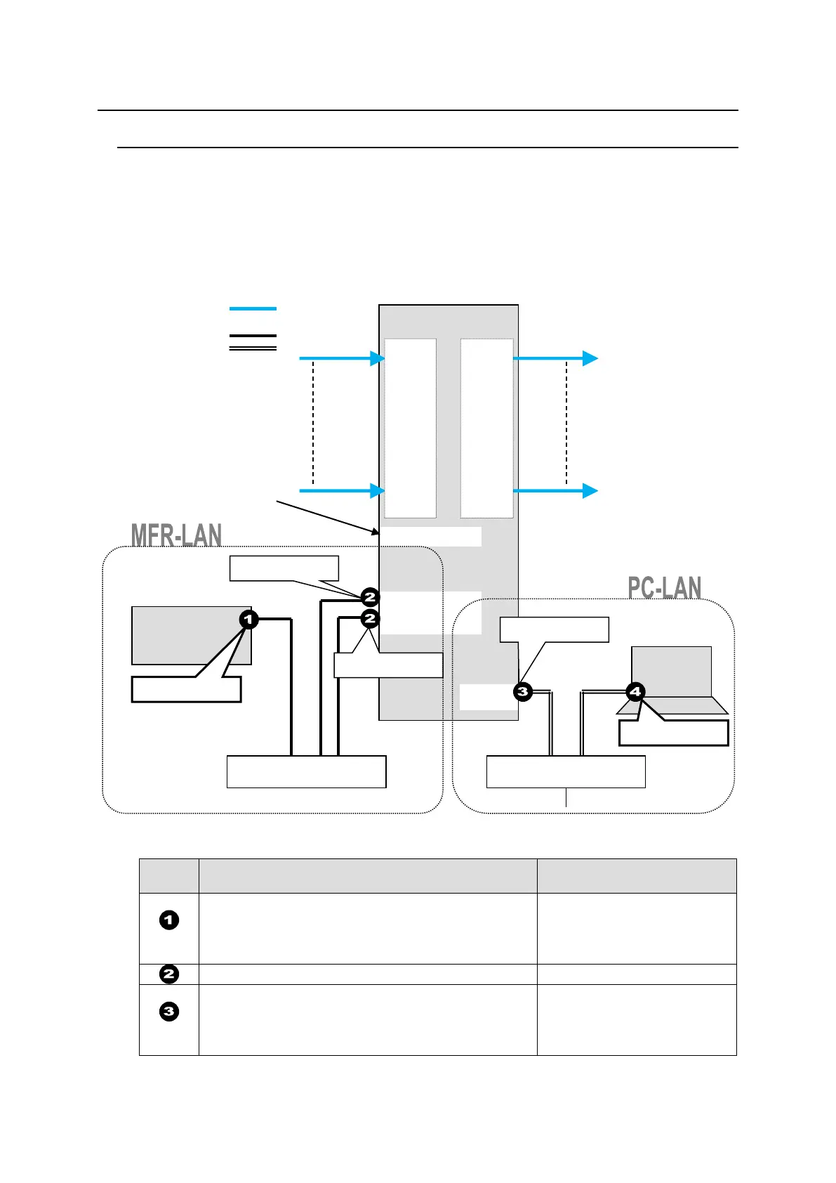
The block diagram below shows an example of the basic MFR routing system that consists of an
MFR Main Unit, Remote Unit and the Web-based Control accessed from a computer.
Make sure to connect both MFR-LANs (CPU1) and (CPU2) to a LAN respectively for CPU
redundancy. Their LAN connections must be separated from the network segment of PC-LAN
and other devices. (Default IP addresses (Net mask: 255.255.255.0) are used in the
configuration example below.)
LAN Port Settings
RU Front Panel
(Sec. in MFR-RU Series Operation Manual)
MFR-39RUA: See sec.3-4-4.
MFR-39RU: See sec. 3-6-1.
MFR-18RU/18RUA: See sec. 3-8-1 and 3-8-2.
Other RUs: See sec. 3-10-1 and 3-10-2.
MFR-39RUA: See sec. 3-4-4 (display only).
MFR-39RU: See sec. 3-6-3 (display only).
MFR-18RU/18RUA: See sec. 3-8-1 (display only).
Other RUs: See sec. 3-10-1 (display only).
IN1
|
|
|
|
I
|
|
I
|
|
I
OUT1
|
|
|
|
I
|
I
|
|
I
I
VIDEO(SDI)
LAN (MFR-LAN)
LAN (PC LAN)
LAN port label indications
have been changed.
New: MFR-LAN (CPU1, 2)
Old: TO RU
New: PC-LAN
Old: TO PC

 Loading...