EasyManuals Logo

FOR-A MFR Series Operation Manuals

FOR-A MFR Series
59 pages
To Next Page IconTo Next Page
To Previous Page IconTo Previous Page
Page #31 background imageLoading...
Page #31 background image
31
3-3-2. Configuration Example 2
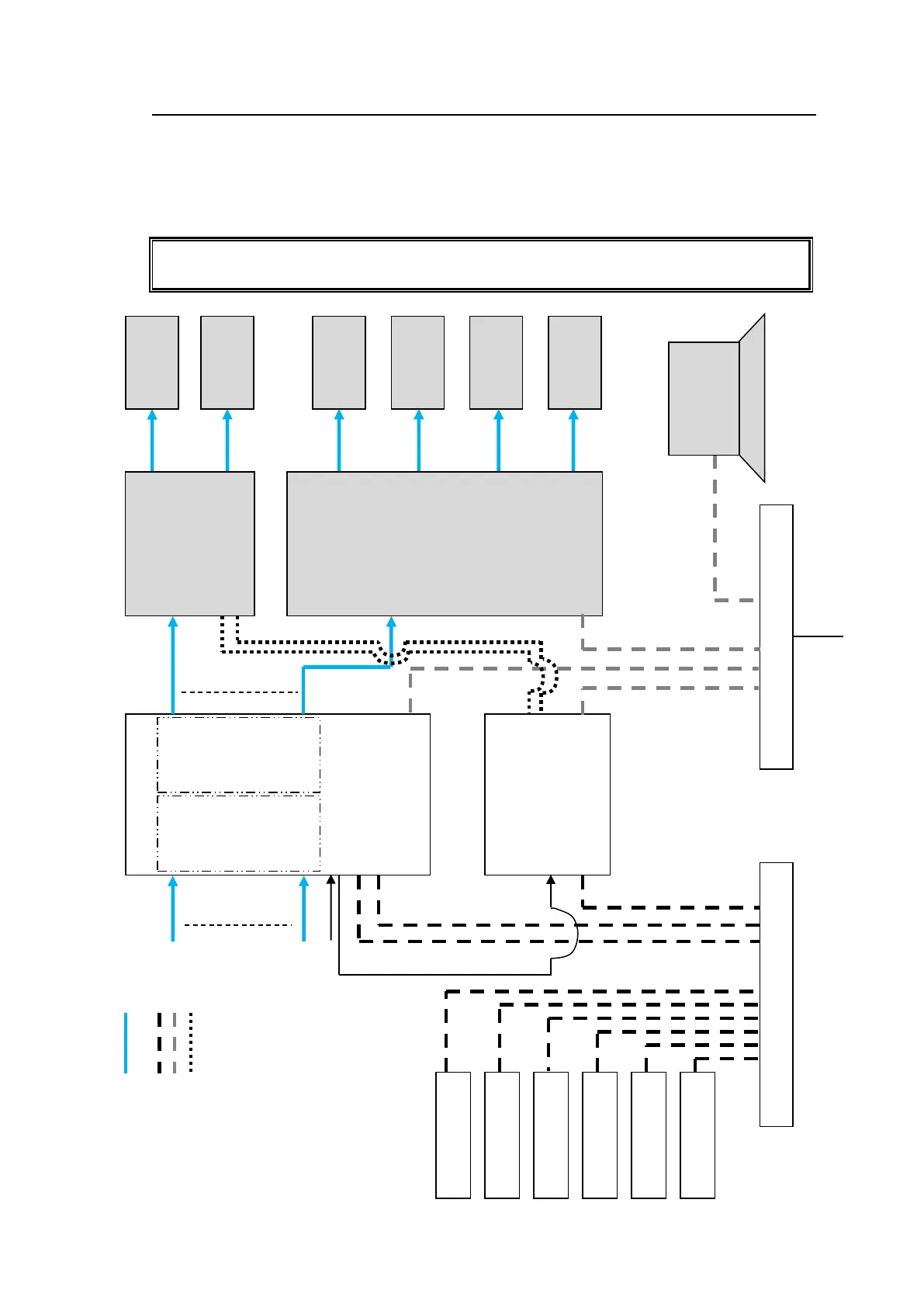
The block diagram below shows an example signal name and tally link system comprised of
a FOR-A video switcher and multiviewer using an MFR-TALM unit. The MFR-TALM is
specifically designed to perform the task of tally data computation, which is ordinarily
undertaken by the MFR main unit, to accelerate the computation. RS-422 ports (1) to (4) are
available for video switcher connection.
Before using an MFR-TALM unit for the system, change Tally Control Unit to MFR-TALM
in the [Main unit Web-based Control: MU Settings page].
Ethernet Hub (PC
-LAN)
DVI
DVI
DVI
DVI
SDI
SDI
OUT1
|
|
|
|
|
|
|
IN1
|
|
|
|
|
|
|
PRV
Monitor
PGM
Monitor
MV
Monitor
MV
Monitor
MV
Monitor
MV
Monitor
VIDEO Switcher
(HVS
-390HS)
Multi Viewer
(MV
-3200)
PC
MFR WEB
MV Layout Editor
MFR
Main Unit
MFR
-LAN
CPU1)
PC-LAN
REF IN
SDI signal
Ethernet Hub(MFR
-LAN)
MFR
-LAN
CPU2)
MFR
-TALM
REF IN
PC-LAN
MFR
-LAN
RS-422 (1)
RS-422 (2)
MFR
-18RU
MFR
-40RU
MFR
-39RU
MFR
-16RUD
MFR
-16RU
MFR
-GPI
BB
SDI signal
VIDEO (SDI, DVI)
LAN
(MFR
-LAN)
LAN (PC LAN)
RS-422
LAN
RS-422 (1)
RS-422 (2)

Other manuals for FOR-A MFR Series

Questions and Answers:

Question and Answer IconNeed help?

Do you have a question about the FOR-A MFR Series and is the answer not in the manual?

FOR-A MFR Series Specifications

General IconGeneral
BrandFOR-A
ModelMFR Series
CategorySwitch
LanguageEnglish

Related product manuals