20
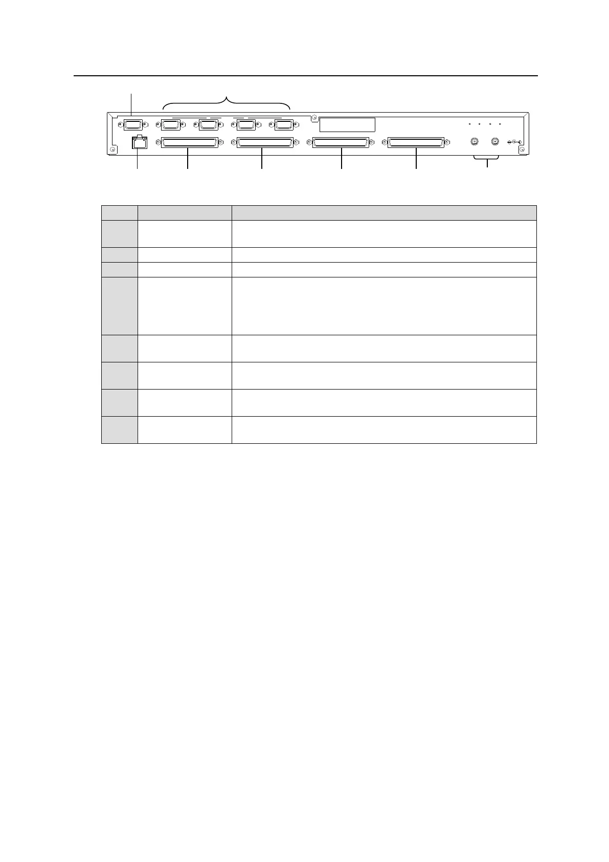
2-2-2. Rear Panel
Used to connect the MFR main unit
Ethernet port (10/100BASE-TX, RJ-45)
Used for maintenance only. Do not use.
Used to supply 12 V DC power.
Used for control via a serial interface. The default setting is
RS-232C. RS-422 is also selectable using switches on the card.
(See section 2-2-4. Switch Settings on the Internal Board.)
Pin assignments are the same as those of the MFR main unit.
(See section 2-1-3. “Interfaces.")
Used for GPI input / output connections.
(32 total assignable inputs and outputs)
Used for GPI input / output connections.
(32 total assignable inputs and outputs)
Used for GPI input / output connections.
(32 total assignable inputs and outputs)
Used for GPI input / output connections.
(32 total assignable inputs and outputs)
*1 The MFR-LAN connector may be labeled 10/100BASE-T on the previous model.
2 -DC12V IN- 1
SERVICE 1 2 3 4
GPI 2GPI 1 GPI 3 GPI 4
RATING LABEL
SERIAL
MFR-LAN

 Loading...