23
2-2-4. Switches on the Card
Do not access internal cards or make connections with the unit powered ON. Always
power OFF all connected units / disconnect power cords prior to accessing the interior.
Further note that adjustments and maintenance should only be performed by qualified
technical personnel familiar with FOR-A equipment.
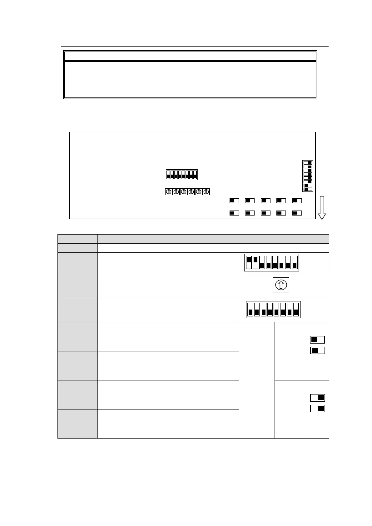
Remove two screws on both sides of the MFR-GPI to access the internal card as shown
below. The figure below shows the factory default switch settings.
Used for maintenance. Do not use.
Used for maintenance. Do not use. (The factory
default setting is as shown at right. The black
boxes (■) represent switches.)
Used for maintenance. Do not use.
Used for maintenance. Do not use.
Used to select RS-232C/RS-422 for SERIAL 1.
Default setting is RS-232C (both switches to the
left). To change to RS-422, set both switches to
the right.
RS-232C
(Factory
default
setting)
Used to select RS-232C/RS-422 for SERIAL 2.
Default setting is RS-232C (both switches to the
left). To change to RS-422, set both switches to
the right.
Used to select RS-232C/RS-422 for SERIAL 3.
Default setting is RS-232C (both switches to the
left). To change to RS-422, set both switches to
the right.
Used to select RS-232C/RS-422 for SERIAL 4.
Default setting is RS-232C (both switches to the
left). To change to RS-422, set both switches to
the right.

 Loading...