EasyManuals Logo

FOR-A MFR Series Operation Manuals

FOR-A MFR Series
59 pages
To Next Page IconTo Next Page
To Previous Page IconTo Previous Page
Page #29 background imageLoading...
Page #29 background image
29
3-3. Signal Name and Tally Link System
3-3-1. Configuration Example 1
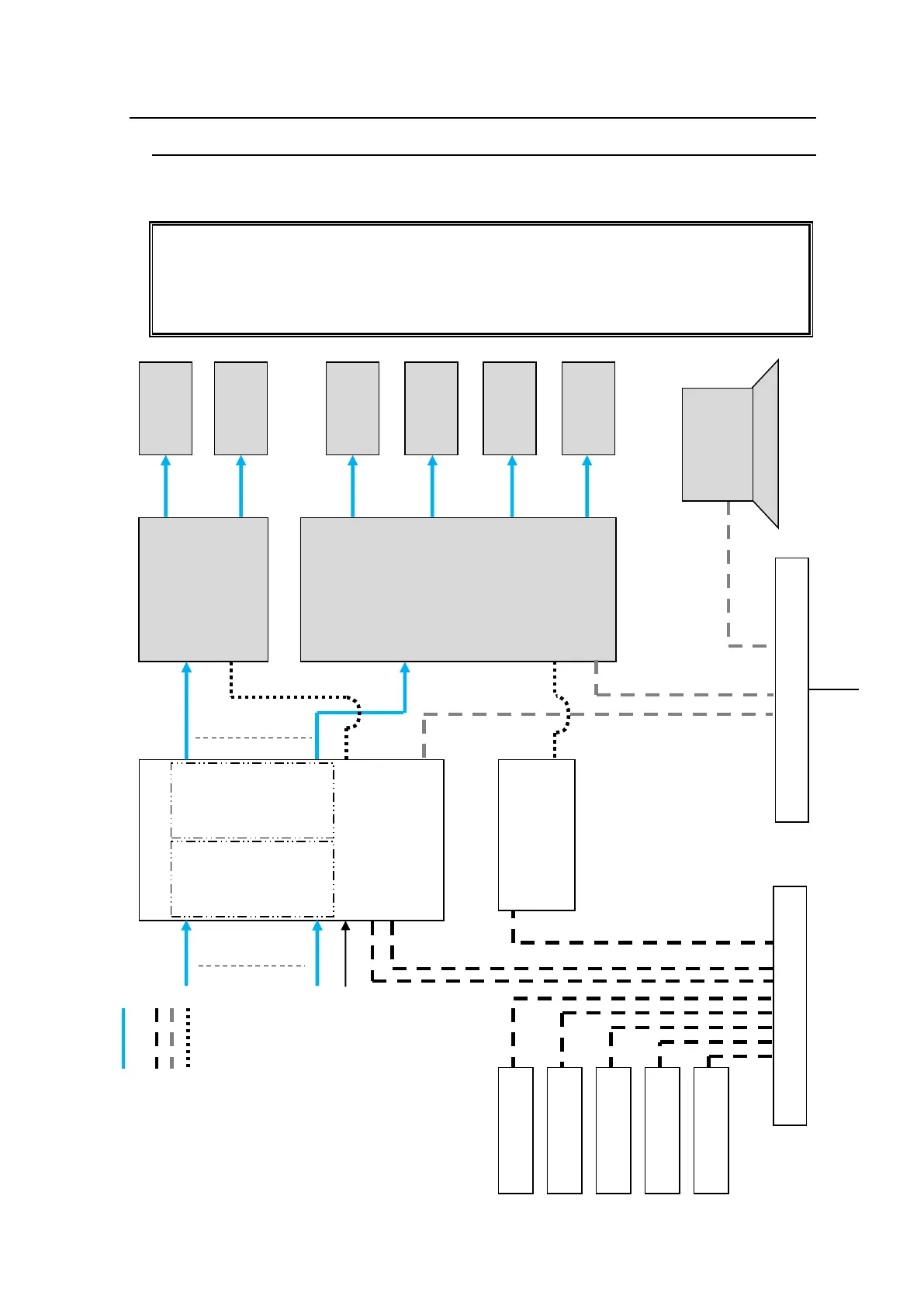
The block diagram below shows an example signal name and tally link system comprised of
a FOR-A video switcher and multiviewer.
To configure this system, connect the SERIAL port on an MFR main unit or SERIAL 1 to 4
on an MFR-GPI unit to the video switcher's serial port. RS-422 ports are required for the
signal name and tally link system. Before connection, change the MFR serial ports from
RS-232C to RS-422 using the internal switches.
See section 2-2-4. "Switches on the Card."
Ethernet Hub (PC
-LAN)
DVI
DVI
DVI
DVI
SDI
SDI
OUT1
|
|
|
|
|
|
|
|
IN1
|
|
|
|
|
|
|
|
PRV
Monitor
PGM
Monitor
MV
Monitor
MV
Monitor
MV
Monitor
MV
Monitor
VIDEO Switcher
(HVS
-390HS)
Multi Viewer
(MV
-3200)
PC
MFR WEB
MV Layout Editor
MFR
Main Unit
MFR
-LAN
CPU1)
PC-LAN
REF IN
SDI signal
Etherne
t Hub(MFR
-LAN)
MFR
-LAN
CPU2)
MFR
-18RU
MFR
-40RU
MFR
-39RU
MFR
-16RUD
MFR
-16RU
MFR
-GPI
BB
SDI signal
LAN
VIDEO (SDI, DVI)
LAN
(MFR
-LAN)
LAN (PC LAN)
RS-422
SERIAL 1
RS-422
SERIAL
SERIAL

Other manuals for FOR-A MFR Series

Questions and Answers:

Question and Answer IconNeed help?

Do you have a question about the FOR-A MFR Series and is the answer not in the manual?

FOR-A MFR Series Specifications

General IconGeneral
BrandFOR-A
ModelMFR Series
CategorySwitch
LanguageEnglish

Related product manuals