EasyManuals Logo

FOR-A MFR Series Operation Manuals

FOR-A MFR Series
59 pages
To Next Page IconTo Next Page
To Previous Page IconTo Previous Page
Page #15 background imageLoading...
Page #15 background image
15
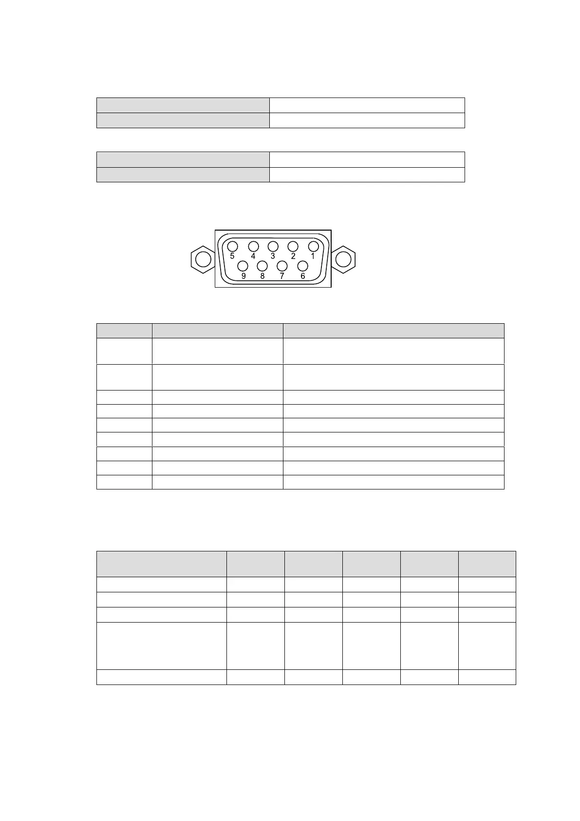
ALARM Connector (9-pin D-sub, female)
Alarm 1 Output:
Under normal operation:
Pins 1 and 6 are open.
In a malfunction or power-off state:
Pins 1 and 6 are closed.
Alarm 2 Output:
Under normal operation:
Pins 2 and 7 are open.
In a malfunction or power-off state:
Pins 2 and 7 are closed.
Reset:
To reset the unit externally, short Pin 5 and a signal ground pin (8 or 9).
ALARM Connector Pin Assignments
Pin No.
Signal Name
Description
1
ALARM1 OUT
Alarm 1 output (Default : FAN)
(Default: POWER on MFR-1616A)
2
ALARM2 OUT
Alarm 2 output (Default: POWER)
(Default: XPT ERROR on MFR-1616A)
3
NC
Not used
4
NC
Not used
5
RESET IN
Reset in, active low
6
ALARM1 COMMON
Alarm 1 output, Common
7
ALARM2 COMMON
Alarm 2 output, Common
8
GND
Signal ground
9
GND
Signal ground
The following items can be set for ALARM1 OUT and ALARM2 OUT. The alarms can be
assigned in the Web-Based Control.
Available alarm signals vary depending on the Main unit model
Alarm signals
3232/
3232RPS
3216/
3216RPS
1616R
1616
1616A
Fan
Available
Available
Available
Available
---
Power
Available
Available
Available
Available
Available
Secondary CPU Error
Available
Available
Available
---
---
CPU Changeover (issued
when the secondary CPU
is activated to change over
the operation)
Available
Available
Available
---
---
Crosspoint Error
Available
Available
Available
Available
Available
9-pin D-sub, female

Other manuals for FOR-A MFR Series

Questions and Answers:

Question and Answer IconNeed help?

Do you have a question about the FOR-A MFR Series and is the answer not in the manual?

FOR-A MFR Series Specifications

General IconGeneral
BrandFOR-A
ModelMFR Series
CategorySwitch
LanguageEnglish

Related product manuals