A- Attaching the cooling system
1- Fit the gantry sides to the two heater rails at the boltholes on
either side of the moulding area with the four nuts and screws
supplied.
2- Fit the Gantry cross member to the top of the gantry sides
with the four nuts and bolts supplied. Mount the fan on the cross
member post so that the fan may be positioned behind the
cross member directing the fan draft forward and away from the
heater.
3- The swivel block is supplied fitted to the fan unit. Slide this onto
the cross member post and tighten the grub screws and locking
nuts. Never fit the fan posts on the underside of the cross member
as the fan may fall and cause injury. Mounting of the fans is a 2
person operation.
4- Adjust the fan unit to the required position and tighten all
the grub screws and lock nuts. Insert her cable into the clips on
the gantry and route the cable down to the fan socket on the
electrical box.
Optional - Cooling system
B- Operating the cooling system
The corresponding FAN button on the touch screen will operate the cooling fan at the appropriate time to
cool the moulding. The button changes colour when operated ON/OFF. It is worth considering the position
of the fan mounting to achieve good and consistent results with different mouldings.
Directing the airflow from behind the cross member down towards the centre of the moulding will reduce
the cooling effect of the fan on the heater.
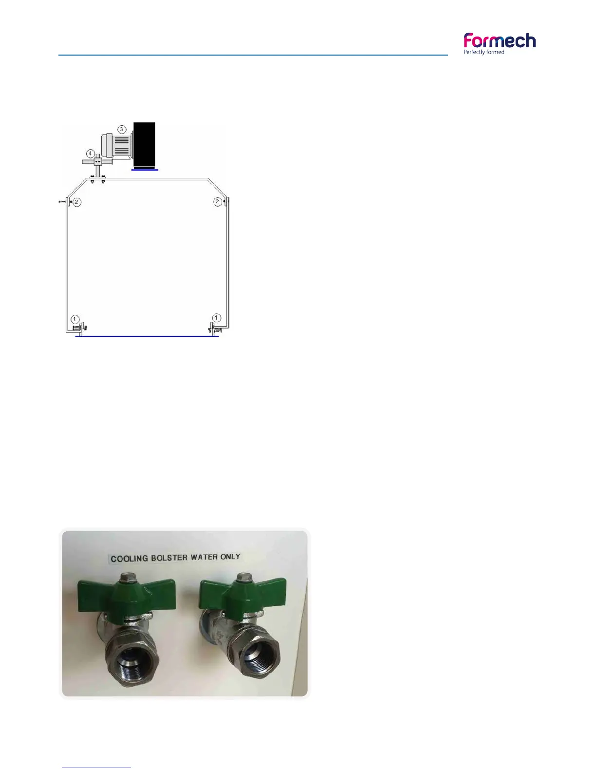
Optional - Connecting the cooling bolster
The cooling Bolster is prefitted to the mould
table. PTFE water pipes are connected between
the underside of the bolster and the back panel.
Connect the feed and return pipes of the
temperature controlled water supply to the 2
fittings mounted on the rear of the machine.
Fitting are are 3/8” BSP.