31
Operation - Other Controls and User Adjustments
Table speed adjustment
Two table speed adjustments are situated on the lower Left hand side of the rear panel (when viewed from
the rear of the machine).
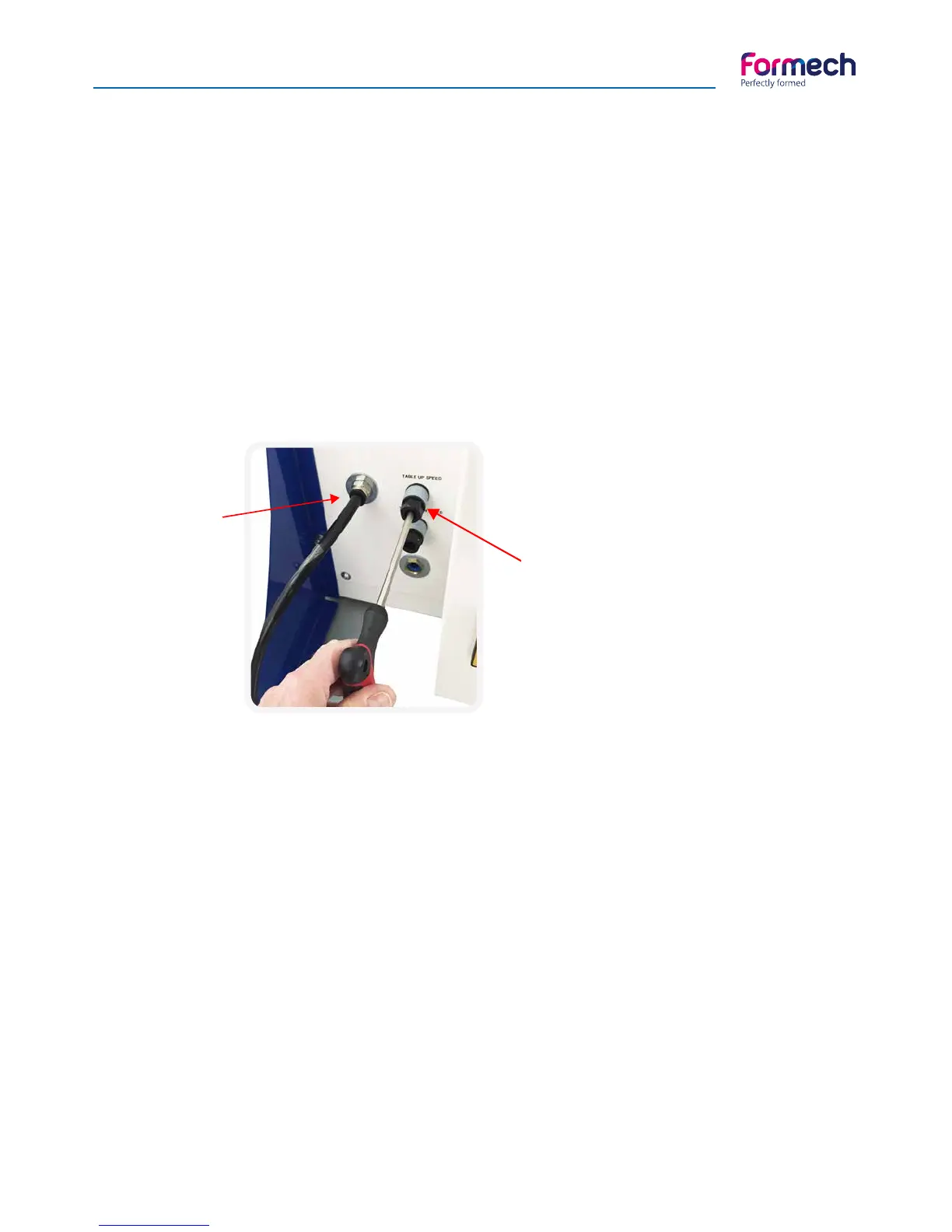
These are flow regulators to adjust the air that is exhausted from the table pneumatic cylinder. Inserting a
6mm hexagon key in the centre and rotating clockwise or anti-clockwise will adjust them (image 1).
Adjust the regulator clockwise to reduce the exhaust flow – to reduce the cylinder speed.
Adjust the regulator anti-clockwise to increase the exhaust flow – to increase the cylinder speed.
The top flow regulator will adjust the table UP speed.
The lower flow regulator will adjust the table DOWN speed.
TAKE CARE WHEN REACHING TO THE BACK OF THE MACHINE. THERE MAY BE VERY HOT SUR-
FACES IN THIS AREA.
Compressed
air inlet
Table
speed flow
regulators
inlet
Clamp frame rear spring adjustment
The clamp frame is spring loaded at the rear. The springs are locked in place with M10 nuts. The loading of
the springs may need to be adjusted, for example, when using thinner or thicker plastics materials to assist
clamping or when a reducing place is fitted.
To adjust the spring loading loosen the lower nut for each spring and adjust the upper nut to suit. Tighten
the lower nut to lock against the upper nut.
TAKE CARE WHEN REACHING TO THE BACK OF THE MACHINE. THERE MAY BE VERY HOT SUR-
FACES IN THIS AREA.
Clamp frame front clamp adjustment
The front material clamps are manually adjustable. Loosen the black thumb screw nut at the base to allow
appropriate adjustment of the top thumbscrew nut. Tighten the lower thumb screw and test that the setting
is correct. Re-adjust as required. Adjustment is required for varying material thickness and reducing plates.