32
Description
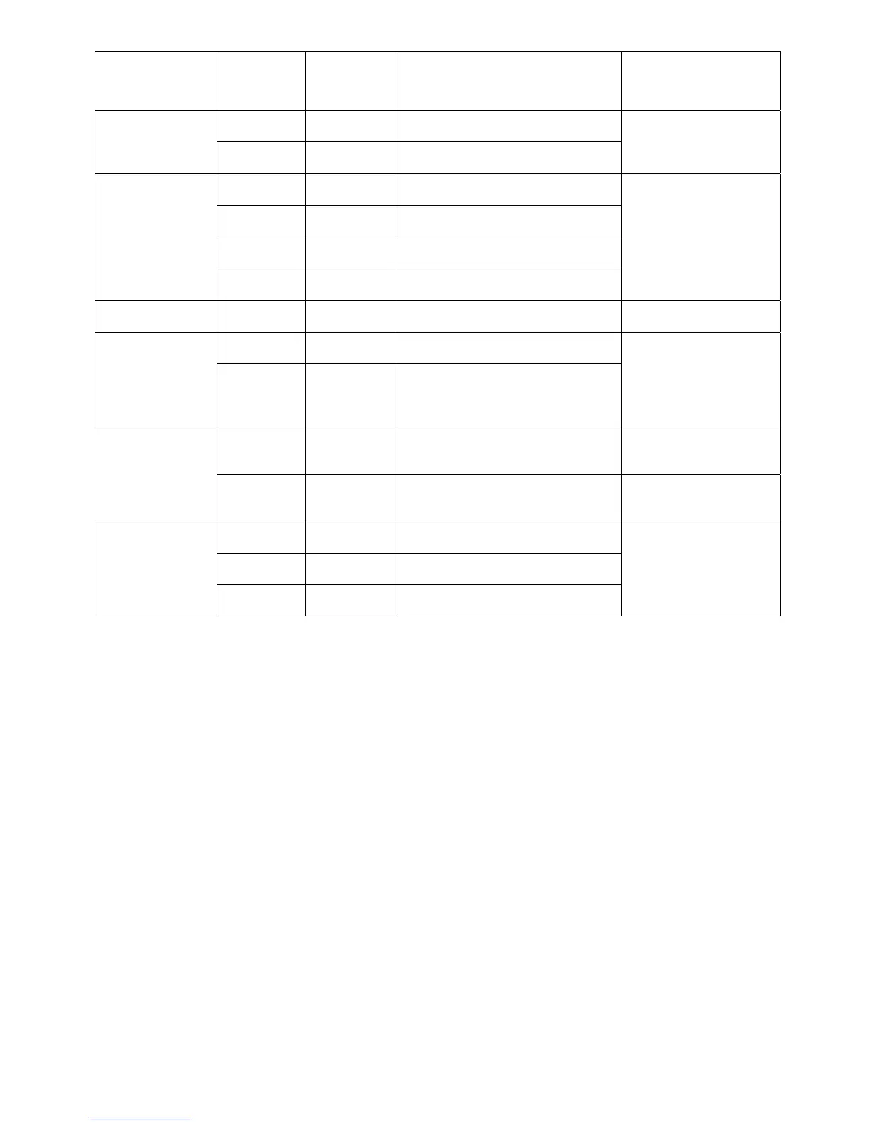
Name Type Description Details
RelayOutput
Terminal
O1 Terminal DefaultSelection:Fault/N.O.
Fault,RunandProofofRun
relay‐SWConfigurable
(1.25A@125VAC,Max
SwitchingVoltage250VAC)
O2 Terminal DefaultSelection:Fault/N.O.
WetInput
Terminals
V1 Terminal1
DefaultSelection:SpeedA/ActiveHigh
(V)
Shutdown/Permissive/
Fireman'sOverride/Limit
Switch/SpeedA/SpeedB
/None‐SWconfigurable
(DefaultN.O.)
12‐240VAC/VDC,5mA
maximum
V2 Terminal1 Common1
V3 Terminal2
WetInput2default:External
Trip/ActiveHigh(V)
V4 Terminal2 Common2
CoolingFan
Fan Connector FanPowerSupply
CoolingfanforVFD
(factorywired)
DryInput
Terminals
D3 Terminal DryInput3default:None
Shutdown/Permissive/
Fireman'sOverride/Limit
Switch/SpeedA/SpeedB
/None‐SWconfigurable
(DefaultN.O.)24VDC3mA
maximum
D4 Terminal DryInput4default:None
AnalogI/O
3A Terminal Input(4–20mA)
AnalogPIDreferenceor
speedreference.MaxError
allowedis1%ofFullScale
SG Terminal SignalGround/Shield
SignalGroundisshared
betweenterminalsD3/D4
and3A
RelayOutput2
03 Terminal DefaultSelection:Fault/N.C.
Fault,RunandStatusrelay
‐SWConfigurable(1.25A
@125VAC,MaxSwitching
Voltage250VAC)
04 Terminal DefaultSelection:Fault/COM
05 Terminal DefaultSelection:Fault/N.O.
Analog Input (1A, SG) - The Analog Input mode is user selectable (0-10V, 0-24V or 4-
20mA) based on status of DIP switches.
Configurable Analog Input/Output (2A, SG) - The Analog Input/Output mode is user
selectable (0-10V input, or output 0-10V or 4-20mA) via DIP switches. When configured
as an input it only accepts an 0-10VDC input signal
. As an output, it provides a
programmable/variable voltage or current.
Analog Input 3A is a dedicated 4-20mA input
Wet Inputs (V1-V2, V3-V4) - Voltage Input accepts AC/DC voltages 12-240V± 10%,
maximum current draw is 5mA. Inputs can be interchanged between N.O. and N.C.
Default state is Active High when voltage is present (N.O.).
Dry Inputs (D1, D2, D3, D4 SG) - Four Dry inputs with maximum current limit of 3mA are
available. Inputs can be interchanged between N.O. and N.C. Default contact state is
NO.
Power Outputs –
o (A+, A-) The Damper Power output will be activated as soon as an active run
command from the VFD is initialized and provides 24V DC at 0.5A maximum. If
a limit switch or a timer is used, the VFD will not output until the switch closes or
timer expires.
(24, SG) The Control Power will output 24VDC at 50mA maximum. The Control Output will be
activated whenever the VFD is powered up to provide controls to sensors