31
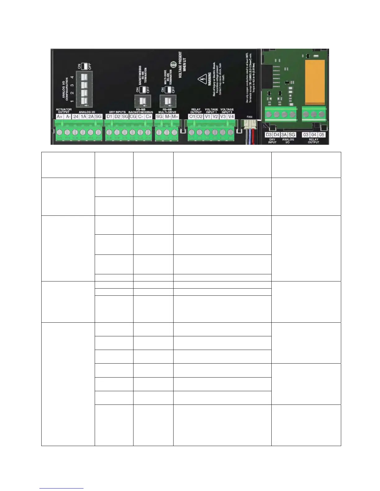
4.8 Digital and Analog Control Circuit Terminal Layout
Description
Name Type Description Details
DamperOutput
A+ Terminal 24VDCDamperoutV+(positive)
24VDCDampersupply,
0.5Amax
A‐ Terminal 24VDCDamperoutV‐(negative)
AnalogIn/Out
24 Terminal 24VDCControlPowerOutput
24VDCsupplycapableof
50mAmaximum.
AnalogPIDreferenceor
speedreference.
MaxErrorallowedis1%of
FullScale
1A Terminal Input(0‐10V/0‐24V/4‐20mA)
2A Terminal ConfigurableInput/Output0‐10V
SG Terminal SignalGround
DryInput
Terminals
D1 Terminal DryInput1default:Run/N.O. Shutdown/Permissive/
Fireman'sOverride/Limit
Switch/SpeedA/SpeedB
/None‐SWconfigurable
Internal24VDC3mA
circuit.
D2 Terminal DryInput2default:None/N.O.
SG Terminal Signalground/Shield
Communications
CG Terminal CommunicationsGround
RS‐485portforModbus
RTUandBACnetMS/TP
Communications
‐ Terminal‐RS‐485
+ Terminal +RS‐485
SG Terminal SignalGround/Shield
Wiringforcommunication
tomultipledrives
M‐ Terminal‐RS‐485
M+ Terminal +RS‐485
E1 CAT5 EthernetPort
CommPortforModbusIP
andBACnetIP(Not
picturedabove–located
belowHOAbuttons,onthe
leftofthecoolingfan
cover)
 Loading...