130 Cyclone PRO User Manual
CYCLONE PRO
PORTB1. In which case the user does not need to connect these signals to
the target MON08 Header. The clock division is fixed Div 4.
An external clock signal must be provided to the target MCU’s OSC pin. The
Cyclone PRO provides this signal to MON08 header Pin 13.
This device has several different algorithms, each of which will program the
calculated trim value to a different non-volatile memory location. Each
algorithm is named to reflect the non-volatile trim location to which it
corresponds, e.g., 908_kx98trim$fdff.08p will program the trim value to
location $FDFF. Simply select the appropriate algorithm when configuring the
Cyclone PRO to ensure that trim is programmed to the desired location.
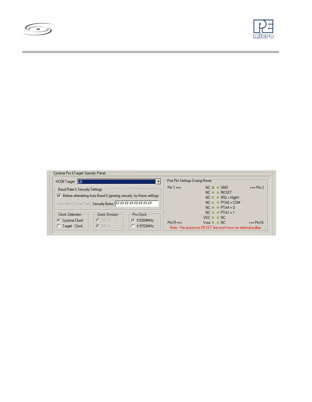
13.22 68HC908LB
Figure 13-22: 68HC908LB Family MON08 Pinout
The target GND is connected to the Pin 2 of the target MON08 Header.
The user must pull up the RESET line to target VDD with an external resistor.
The target IRQ line is directly connected to the Pin 6 of the target MON08
Header.
PORTA0 from the target processor is connected to the target MON08 Header
Pin 8, acting as the communications line. The Cyclone PRO pulls up this
signal with a 10K Ohm resistor to the target VDD.
PORTA1 and PORTA4 are used for entering monitor mode. By default the
user may directly bring these signals out to the target MON08 Header.
Alternatively, the user may pull up PORTA1 and pull down PORTA4. In which
case the user does not need to connect these signals to the target MON08
Header. The clock division is fixed Div 4.