Cyclone PRO User Manual 131
CYCLONE PRO
An external clock signal must be provided to the target MCU’s OSC pin. The
Cyclone PRO provides this signal to MON08 header Pin 13.
Please note that the Cyclone PRO will calculate the proper trim value for the
device being programmed. The user has the option to program this trim value
to $FFC0.
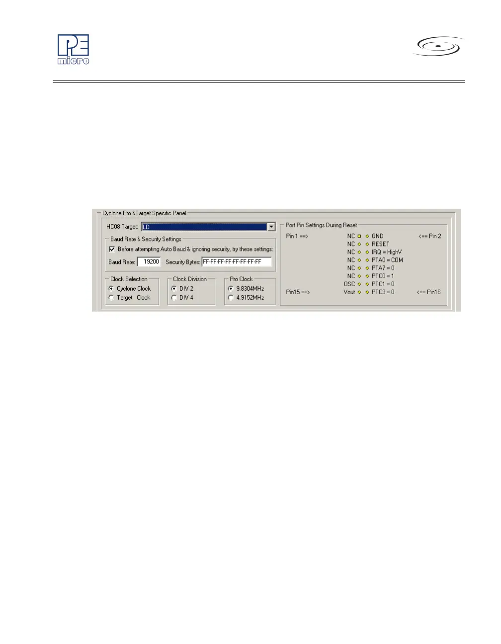
13.23 68HC908LD
Figure 13-23: 68HC908LD Family MON08 Pinout
The target GND is connected to the Pin 2 of the target MON08 Header.
The target RESET line is directly connected to the Pin 4 of the target MON08
Header.
The target IRQ line is directly connected to the Pin 6 of the target MON08
Header.
PORTA0 from the target processor is connected to the target MON08 Header
Pin 8, acting as the communications line. The Cyclone PRO pulls up this
signal with a 10K Ohm resistor to the target VDD.
PORTA7, PORTC0, PORTC1 and PORTC3 are used for entering monitor
mode. By default the user may directly bring these signals out to the target
MON08 Header.
Alternatively, the user may pull up PORTC0, pull down PORTA7 and
PORTC1, and pull up/down PORTC3 for clock division. In which case the
user does not need to connect these signals to the target MON08 Header.