Cyclone PRO User Manual 11
CYCLONE PRO
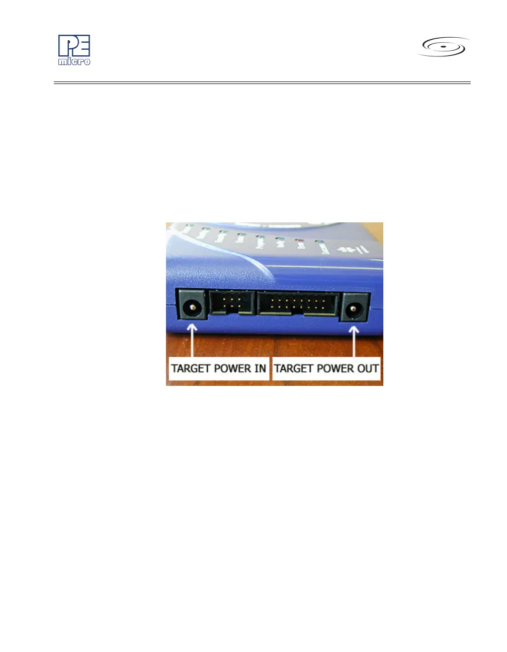
3.6 Power Connectors
The Cyclone PRO provides a Target Power Supply Input Jack and a Target
Power Supply Output Jack with 2.5/5.5 mm Pin Diameter. The power jacks
are connected or disconnected by two electromechanical relays. When
connected, the Center Pin of the Target Power Supply Input Jack is
connected to the Center Pin of the Target Power Supply Output Jack. When
disconnected, both terminals of the Target Power Supply Output Jack are
connected to GND via a 1W, 100 Ohm resistor.
Figure 3-6: Power Connector Locations
3.7 Jumper Settings
Please note that Rev. C of the Cyclone PRO uses different jumper settings
than previous revisions. The jumpers must be set differently for various power
management options that the Cyclone PRO offers. If the Cyclone PRO is not
being used to manage the target’s power, only Jumper 5 needs to be
installed. Please see Section 3.12 - Target Power Management for the
correct jumper settings for other power management options.