FRICK QUANTUM EVAPORATOR CONTROL PANEL S90-600 O
OPERATION Page 7
INITIAL SETUP PROCEDURE
1. “Panel Setup” is performed first. “Panel Setup” is
used to setup panel features and options that later
can be changed by an operator. Features such as the
panel time, and screen color are changed here.
2. “Zone Board Setup” is performed next. “Zone Board
Setup” is used to setup the customer specific control
features and options to be used by a zone controller
board. This setup should not need to be changed by
operators. “Zone Board Setup” is intended to be
accessed and performed only by a Factory
Representative or Distributor.
3. Calibrate the control devices.
4. From Control Setup enter and setup the control
settings.
5. From Security Setup, establish the desired access
rights of the operators.
6. From the “Zone Overview – 2” screen, select the most
important information you want to view.
The panel now provides quick access to the most
important information and controls of the zones and their
subsystems.
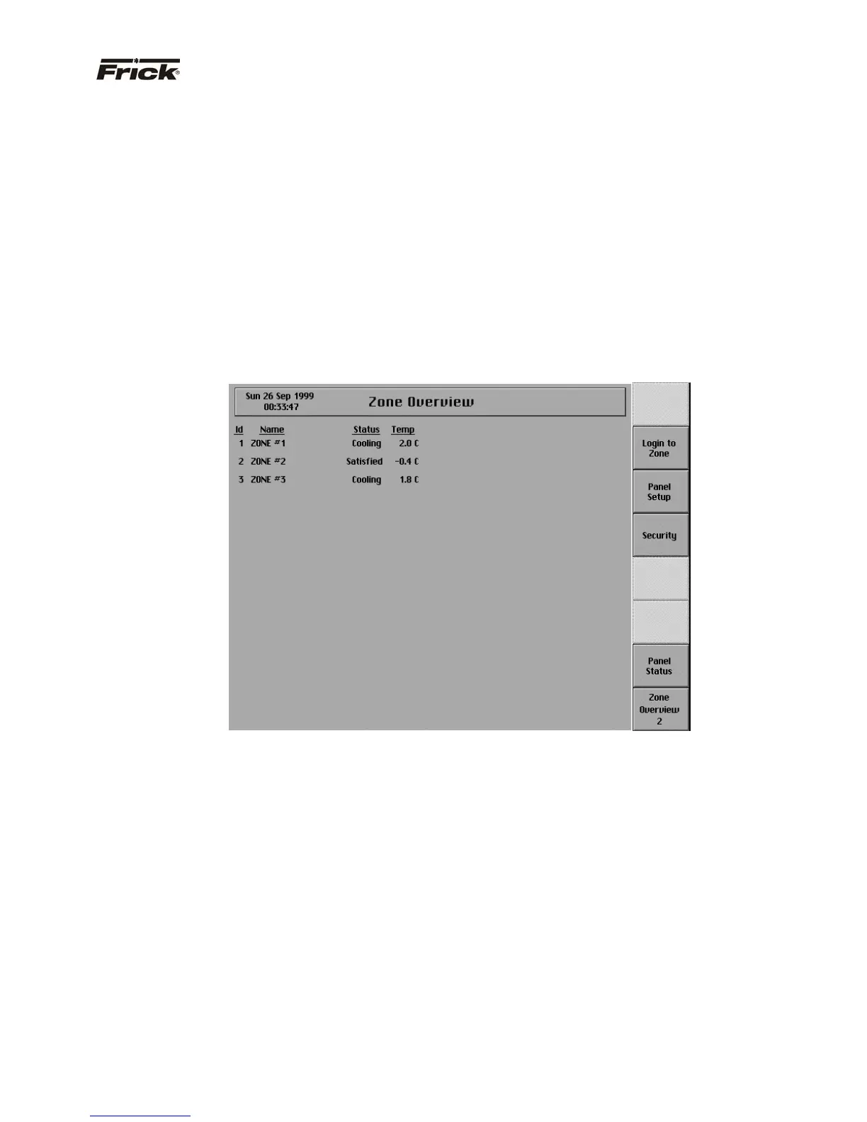
GRAPHIC SCREENS
“ZONE OVERVIEW” SCREEN
Also called the “Home” screen. This screen shows an
overview of the most important information about the
zones. This screen is shown when power is first turned on
and when a key is pressed after the screen saver has
turned off the backlight. The “Zone Overview” screen is
continuously updated and provides the current status of
each zone's condition and performance.
The following information is shown on this screen:
· ID - The identification number of the zone
displayed.
· Name - The identification name that describes
the zone that is displayed.
· Status – The present operation status of the
zone.
· Temperature - The present temperature reading
of the zone’s control point.
Several types of failures and alarms are also indicated on
this screen. If a zone stops communicating with the
Quantum™, the information specific to that zone is shown
in red text. After communication with the zone has been
restored, the text color will return to black. In addition, a
list of the units that have previously been communicating
with the Quantum™ is saved even when the Quantum™
is powered off. If a unit in that list does not respond to the
Quantum™ during the Quantum’s™ starting sequence,
the words “Not Found” are displayed in red in place of that
unit’s name. Once a proper connection with the unit is
made, logging in to the unit will replace the words “Not
Found” with the unit’s name. Finally, when a unit is in an
alarm condition, the control temperature for that unit will
be displayed as a flashing, red value until the alarm is
cleared.