EasyManuals Logo

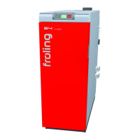
Froling P2-25 User Manual

Froling P2-25
80 pages
To Next Page IconTo Next Page
To Previous Page IconTo Previous Page
Page #48 background imageLoading...
Page #48 background image
Installers and service technicians
Electrical Connection
Page 48
B0190806
s
7
7 Installers and service technicians
7.1 Connection layout of the boards
A
W
W
W
H
H
H
PEL
L
L1
L1
+L
+L
+R
+R
P2
P2
Y/P3
Y/P3
+US
+US
GND
GND
RXD
RXD
TXD
TXD
N
Mains
ID Fan
Pump 2
Pump 1
Pump 3
Burner/
HCP 0
Primary air
DCS
Door contact switch
Sensor 3
Sensor 2
Sensor 1
Sensor 4
Sensor 5
0
N
PE1 PE2
A
W
H
A
A
HCP/ Oil
Lambda
board
3100
(optional)
View of lower level
3100
control
Ribbon cable
to extension board 1
L
N
L
N
L
N
L
N
whi 12VAC
-
black
+
PEL
Power supply of motherboard
NL LL
D
I
S
P
L
A
Y
E
P
R
O
M
Trans-
former
Pump 1
Pump 3
NLLL
NE1
LE1
NE2LE2
Pump 2
Blower
NL, LL, PEL ....Power supply for the
Lambda board
NE1, LE1, PE1 ....Power supply for
extension board 1
Mother
board
3100
W
H
A
JP2
JP1
Follow the connection instructions!
Lambda
probe
e.g.: RGB,
visualisation
e.g.: Pellet
module
User
extension
Device
extension
green-yellow
blue
red
Flue gas sensor
Boiler sensor
FG Sensor
BS Sensor
Side view of switch
Manual
BLOWER
PUMP 3
PUMP 2
PUMP 1
HEATING 4
HEATING 3
HEATING 2
HEATING 1
HEATING 0/ OIL
Power supply
Power supply
for pellet module
Secondary
air
Manual (M) - WHITE
Root (R) - BROWN
Automatic (A) - VIOLET
Ribbon cable
to extension board 2
NE2, LE2, PE2 ....
extension board 2
Power supply for
whi 12VAC

Table of Contents

Questions and Answers:

Question and Answer IconNeed help?

Do you have a question about the Froling P2-25 and is the answer not in the manual?

Froling P2-25 Specifications

General IconGeneral
BrandFroling
ModelP2-25
CategoryBoiler
LanguageEnglish

Related product manuals