What happens when AC frequency is too high on Fronius Inverter?
- BBrenda LoveSep 6, 2025
If the AC frequency is too high, the Fronius Inverter will resume feeding energy into the grid.

What happens when AC frequency is too high on Fronius Inverter?
If the AC frequency is too high, the Fronius Inverter will resume feeding energy into the grid.
What to do if error occurred during update process of Fronius Inverter?
If an error occurred during the update process of your Fronius Inverter, re-download the update file. If the status code is still displayed, notify a Fronius-trained service engineer.
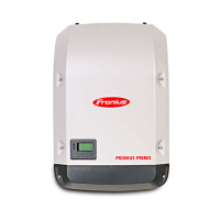
What happens when AC voltage is too high on Fronius Primo 5.0-1 AUS?
If the AC voltage is too high, the Fronius Inverter will resume feeding energy into the grid.
What happens when internal temperature is too high on Fronius Inverter?
When the internal temperature of your Fronius Inverter is too high, the inverter resumes with its start-up routine.
How to resolve functional incompatibility on Fronius Primo 5.0-1 AUS Inverter?
To resolve functional incompatibility on your Fronius Inverter, update the inverter firmware. If the status code is still displayed, notify a Fronius-trained service engineer.
What to do if Fronius Primo 5.0-1 AUS shows no communication with power stage set?
If your Fronius Inverter displays a status code indicating no communication with the power stage set continuously, notify a Fronius-trained service engineer.
How to fix invalid limit value settings on Fronius Inverter?
To address invalid limit value settings on your Fronius Inverter, update the inverter firmware. If the status code continues to appear, notify a Fronius-trained service engineer.
What causes LOW PV VOLTAGE on Fronius Primo 5.0-1 AUS?
The 'LOW PV VOLTAGE' status code on your Fronius Inverter may appear due to the low level of insolation. If this status code occurs when there is sufficient insolation, contact your system engineer.
Why is my Fronius Primo 5.0-1 AUS showing LOW PV OUTPUT?
A 'LOW PV OUTPUT' status code on your Fronius Inverter can be due to the low level of insolation. However, if this code appears when there is sufficient insolation, contact your system engineer.
What to do if Fronius Inverter shows Overcurrent (AC) error?
The fault should rectify automatically. However, if the Fronius Inverter continuously displays this status code, you should notify a Fronius trained service engineer.
| AC nominal output | 5.0 kW |
|---|---|
| Max. output current | 21.7 A |
| Max. input voltage | 1000 V |
| Number of MPPT | 2 |
| Dimensions (W x H x D) | 431 x 645 x 204 mm |
| Weight | 21.5 kg |
| Protection class | IP65 |
| Max. apparent AC power | 5.0 kVA |
| AC nominal voltage | 230 V |
| AC voltage range | 180 - 270 V |
| Frequency | 50 Hz |
| THD | < 3% |
| DC input voltage range | 200 - 800 V |
| Max. inverter efficiency | 98.1% |
| CEC efficiency | 97.5 % |
| Night consumption | < 1 W |
| Ambient temperature range | -25°C to +60°C |
| MPPT Voltage Range | 200 - 800 V |
| Installation location | Indoor and outdoor |
| Max. permissible humidity | 0 - 100 % |
| AC connection | Screw terminal |
| Certificates and standards | IEC 62109-1, IEC 62109-2, IEC 62116 |
| Warranty | 5 years |
Covers personnel qualification, environmental conditions, and general safety precautions.
Details requirements and responsibilities for qualified service personnel.
Explains the meaning of WARNING, CAUTION, and NOTE symbols used in the manual.
Details the inverter's design, components, and core functionality.
Defines proper usage, prohibited actions, and on-device warning notices.
Introduces the Fronius Solar Net data network and its interface.
Overview of the inverter's system monitoring capabilities and functions.
Steps for connecting the inverter and enabling the Wi-Fi access point.
Identifies the physical controls, display screen, and status LEDs on the inverter.
Explains the meaning of the red, orange, and green status LEDs.
Describes the purpose and usage of the navigation and selection keys.
Covers pre-configuration and user-defined settings adjustments.
Step-by-step guide to updating the inverter software.
Explains the purpose and functionality of the inverter's key lock.
Step-by-step guide to activate or deactivate the key lock.
Step-by-step instructions to enter the Basic menu with an access code.
Instructions for safely disconnecting AC and DC power to the inverter.
Explains how faults are shown and what status codes mean.
Information on DC isolation, overload, and anti-islanding methods.


