23
I
2
I
1
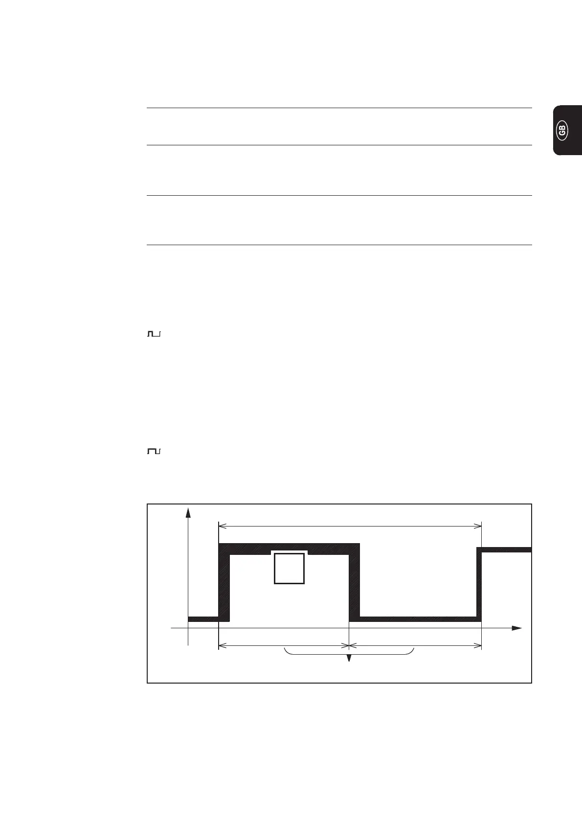
Duty-Cycle
0
I
t
T= 1/f
(Hz)
50% 50%
Fig. 23 Setting-example Duty-Cycle in scale position "50"
With the TR 50mc remote control pulsing unit two operational modes are possible:
- Regulation of impulse current I
1
by TR 50mc remote control unit.
- Adjustment of impulse current I
1
by means of the TR 52mc remote control pedal
unit.
(23) Pulsing current dial I
1
(main current)
- For continuous adjustment of the pulsing / main current
(24) Pulse frequency dial f (Hz)
- For continuous adjustment of the pulse frequency, depen-ding on which
frequency range has been preselected by switch (27).
(25) Background current dial I
2
- The setting for the background current is made as a percentage of the value
set for the pulsing current I
1
(26) Duty-Cycle dial %
- Setting dial for pulse / interval relationship = this dial is for setting the relati-
onship, in percentage terms, between the pulsing current phase and the
background current phase.
Setting-examples
Duty cycle dial (26) is in scale position 10,
- Short pulsing current phase of 10 %
- Long background current phase of 90 %
- Low degree of heat impact.
Duty Cycle dial (26) is in scale position 50, (see Fig.23)
- Pulsing current phase and background current phase are equally long (each 50
%)
l Means medium degree of heat impact.
Duty cycle dial (26) is in scale position 90,
- Long pulsing current phase of 90 %
- Short background current phase of 10 %
- High degree of heat impact.
TR 50mc remote
control pulsing
unit
(contiued)
 Loading...


