31
EN
(4) Welding voltage indicator
lights up when welding parameter I
1
is selected. During welding the current actual value for the welding voltage is dis-
played on the right-hand digital display.
Before welding, the following appears on the right digital display:
- 0.0 if a TIG welding mode is selected
- 50 V if a MMA welding mode is selected (after a delay of 3 seconds; 50 V is the
average value for the pulsed open circuit voltage)
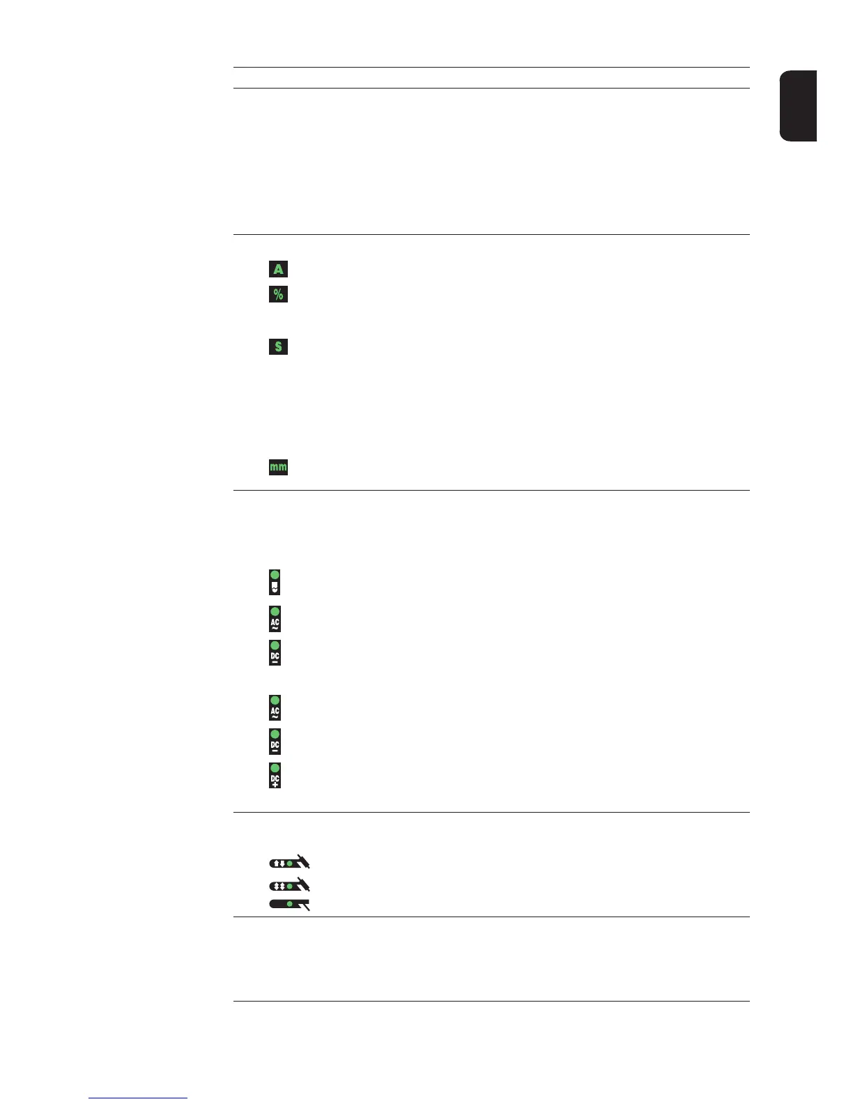
(5) Unit indicators
A indicator
% indicator
lights up when the I
S
, I
2
and I
E
welding parameters and the dcY, I-G and
HCU set-up parameters have been selected
s indicator
lights up when the t
up
and t
down
welding parameters plus the following set-
up parameters have been selected:
- GPr
- G-L
- G-H
- UPS
- tAC
- Hti
- HFt
mm indicator
lights up when the Fdb set-up parameter has been selected
(6) Process button
for selecting the welding process depending on the mode that has been chosen
2-step mode/4-step mode:
automatic cap-shaping;
only available in conjunction with TIG AC welding
TIG AC welding process
TIG DC- welding process
Manual metal arc welding mode:
MMA AC welding process
MMA DC- welding process
MMA DC+ welding process
When a process is selected, the LED on the relevant symbol lights up.
(7) Mode button
for selecting the mode
2-step mode
4-step mode
Manual metal arc welding
(8) Right parameter selection button
for selecting welding parameters within the welding parameters overview (11)
When a welding parameter is selected, the LED on the relevant parameter symbol
lights up.
No. Function
 Loading...