4 Ke
pad Panel 4-1
FVR-C11S-EN
4
4Ke
pad Panel
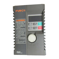
4-1 Names and Functions
Di
ital displa
In pro
ram mode: Shows function codes and data
codes.
In Operation mode: Shows the output frequenc
and output current, etc.
In Trip mode: Shows a code indicatin
the causes
of the trip.
Pro
ram (Reset) ke
Switches between Operation mode and Pro
ram
mode.
In Trip mode: Resets the trip status and chan
e
to Operation mode.
Function/Data ke
In Operation mode: Switches between frequenc
displa
and output current displa
durin
stopped
and runnin
. In Pro
ram mode: Used to read and
write various function codes and function data
items.
Up/down ke
s
In Operation mode: Used to increase and reduce
the frequenc
(motor speed).In Pro
ram mode:
Used to chan
e a function code and data value.
RUN ke
This ke
is used to start operation.
The LED is on durin
operation.
This ke
does not function when the data code
from the external si
nal (di
ital input) is selected
(F02 = 1).
STOP ke
This ke
is used to stop operation.
This ke
does not function when the data code
from the external si
nal (di
ital input) is selected
(F02 = 1).
4-2 Operatin
Ke
pad Panel
1) Switchin
monitor
The displa
can be switched between fre-
quenc
displa
and output current displa
b
pressin
the in Operation mode.
1) Frequenc
is displa
ed as a percenta
e with the least
si
nificant di
it in PID control operation (function H20
is set to 1 or 2):
for 10%
for 100%
2) The reference frequenc
is displa
ed when the
ke
is pressed in current indication.
2) Stoppin
operation
Operation is started when the is
pressed, and is stopped when the is
pressed while function is set to a val-
ue other than .
The rotation direction is:
= : Forward rotation with
FWD-P24/CM ON, and
reverse rotation with
REV-P24/CM ON
= : Forward rotation
(FWD/REV input is i
-
nored.)
= : Reverse rotation
(FWD/REV input is i
-
nored.)
60.0 1. 2 A
1
0.
100.
F02
1
F02 0
F02 2
F02 3
Frequenc
1
Current
2

 Loading...


