● Controller LEDs
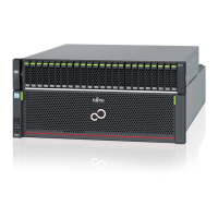
Figure 19 shows the LEDs of the controller. Table 7 shows the status and meanings of each LED.
Figure 19 Controller LEDs
1. READY LED
2. FAULT LED
3. LAN ACCESS LED
4. LAN LINK LED
5. MASTER LED
6. IDENTIFY LED
7. DI (OUT) FAULT LED
8. DI (OUT) LINK LED
The LEDs turn on or blink to indicate the statuses that are listed below.
Table 7 Status and Meanings of Each LED (Controller)
LED name LED status Meanings
READY
(green)
The controller is in normal status.
(blinks green)
An error has occurred during startup.
FAULT
(amber)
(blinks amber)
•
The controller is in error status.
•
An error has occurred during startup.
LAN ACCESS
(blinks green)
Data is being sent or received via the LAN port (for operation
management).
LAN LINK
(green)
The link between the LAN port (for operation management) and
the destination has been established.
MASTER
(green)
The controller is set as a Master CM.
IDENTIFY
(blinks blue)
As ordered via ETERNUS Web GUI or ETERNUS CLI, the installation
location of the controller is identified.
DI (OUT) FAULT
(amber)
•
The link between the DI (OUT) port and the destination port is
in error status.
•
The ports to remove the mini SAS HD cables between enclo-
sures from are indicated. This occurs while a drive enclosure is
being added.
(blinks amber)
The ports to connect the cables are indicated. This occurs while a
drive enclosure is being added.
DI (OUT) LINK
(green)
The link between the DI (OUT) port and the destination port has
been established.
1. Component Names and LED Names
Controller Enclosures
25
FUJITSU Storage ETERNUS DX500 S4/DX600 S4, ETERNUS DX500 S3/DX600 S3 Hybrid Storage Systems
Operation Guide (Basic)
Copyright 2018 FUJITSU LIMITED
P3AM-7742-12ENZ0

 Loading...