EasyManuals Logo

G-Tek CR-2010 PRO Series User Manual

Default Icon
48 pages
To Next Page IconTo Next Page
To Previous Page IconTo Previous Page
Page #20 background imageLoading...
Page #20 background image
19
Installation
Table 2 Sensor wiring
Sensor Type
Pin numbers of connector
1
2
3
RTD (PT-100) 3-Wire
Red (+)
White (-)
White
RTD (PT-100) 2-Wire
Red (+)
White (-)
Short link between 2 and 3
Thermocouple
Positive (+)
Negative (-)
NC
mV
Positive (+)
Negative (-)
NC
mA
Positive (+)
Negative (-)
NC
Note:
1. Pin No 1 ,2,3 are shown in the above figure 9.
2. When wiring RTDs, lead length and diameter must be chosen such that lead length are equal and
that each lead exhibits no more than 10ohm resistance between the recorder and the RTD (Pt-100).
3. For Input connections, high quality, low resistance contacts must be used which are suitable for
dry operations.
4.The sensor wire connections mentioned in above table will remain same for all the channels.
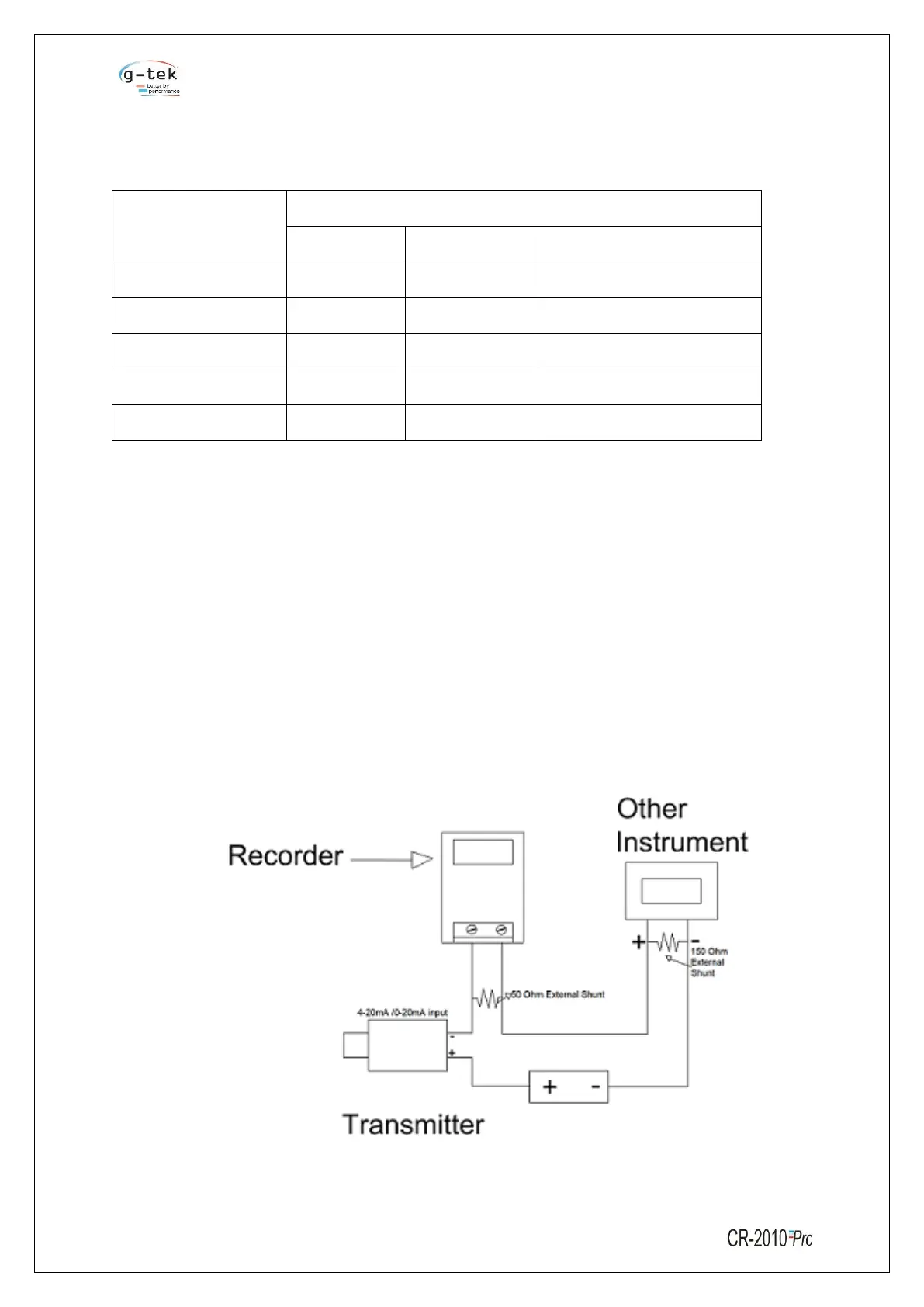
5. Provide 50 Ohm External Shunt resistance between Pin No 1 & 2 while using 4-20 mA/0-20 mA.
Connecting Transmitter with recorder & other instrument using External Power Supply: -
Figure 10 - Connecting Transmitter with recorder & other instrument using External Power Supply

Table of Contents

Questions and Answers:

Question and Answer IconNeed help?

Do you have a question about the G-Tek CR-2010 PRO Series and is the answer not in the manual?

G-Tek CR-2010 PRO Series Specifications

General IconGeneral
BrandG-Tek
ModelCR-2010 PRO Series
CategoryMeasuring Instruments
LanguageEnglish

Related product manuals