Figure B
Figure 7 - Power supply PCB
• The connection for Mains supply is shown in figure A. As per the figure the live, neutral &
earth from the mains cord are connected to L, N & E respectively. Ensure that the bared ends
of the mains cord are fully inserted into the mains connector and no loose/poor connection.
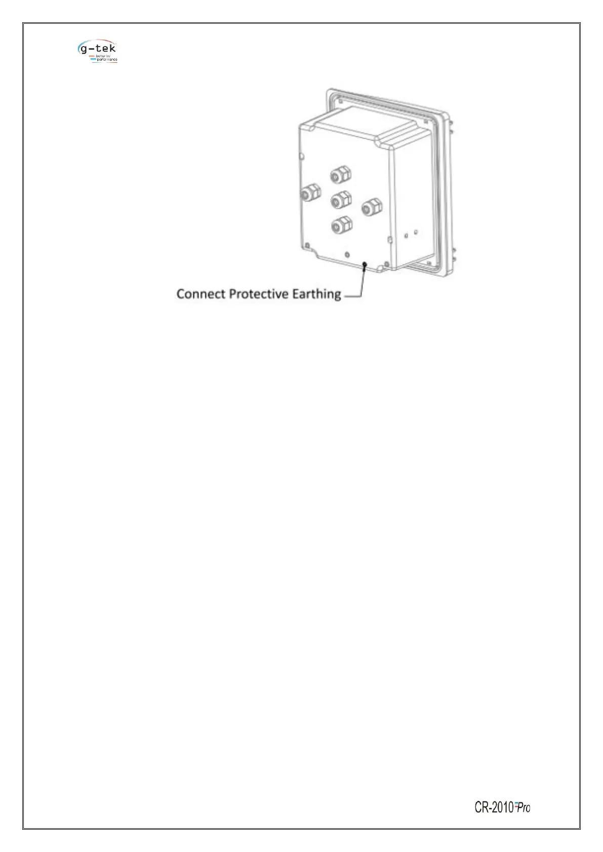
Also connect the Earth wire of the cable to the Earthing terminal given on body of the recorder
as shown in figure B.
• The connection of 12V DC battery is shown in figure 7 Connect the’+’ and’-' of 12V battery to
the’+’ and ‘-’ terminal of the connector respectively.
• Relay connection provided for connecting alarm indicating devices like buzzer, hooter etc. in
the industry, to indicate temperature variation above or below the set points as shown in
above figure.
Note:
* Use 2.5sq.mm. Wire maximum
* Relay Contact ratings are 230VAC – 1Amp. Resistive.
* Use of appropriate snubber Circuit is recommended for
inductive loads.
 Loading...