4.1.2.3 Sensor wiring for different sensor types
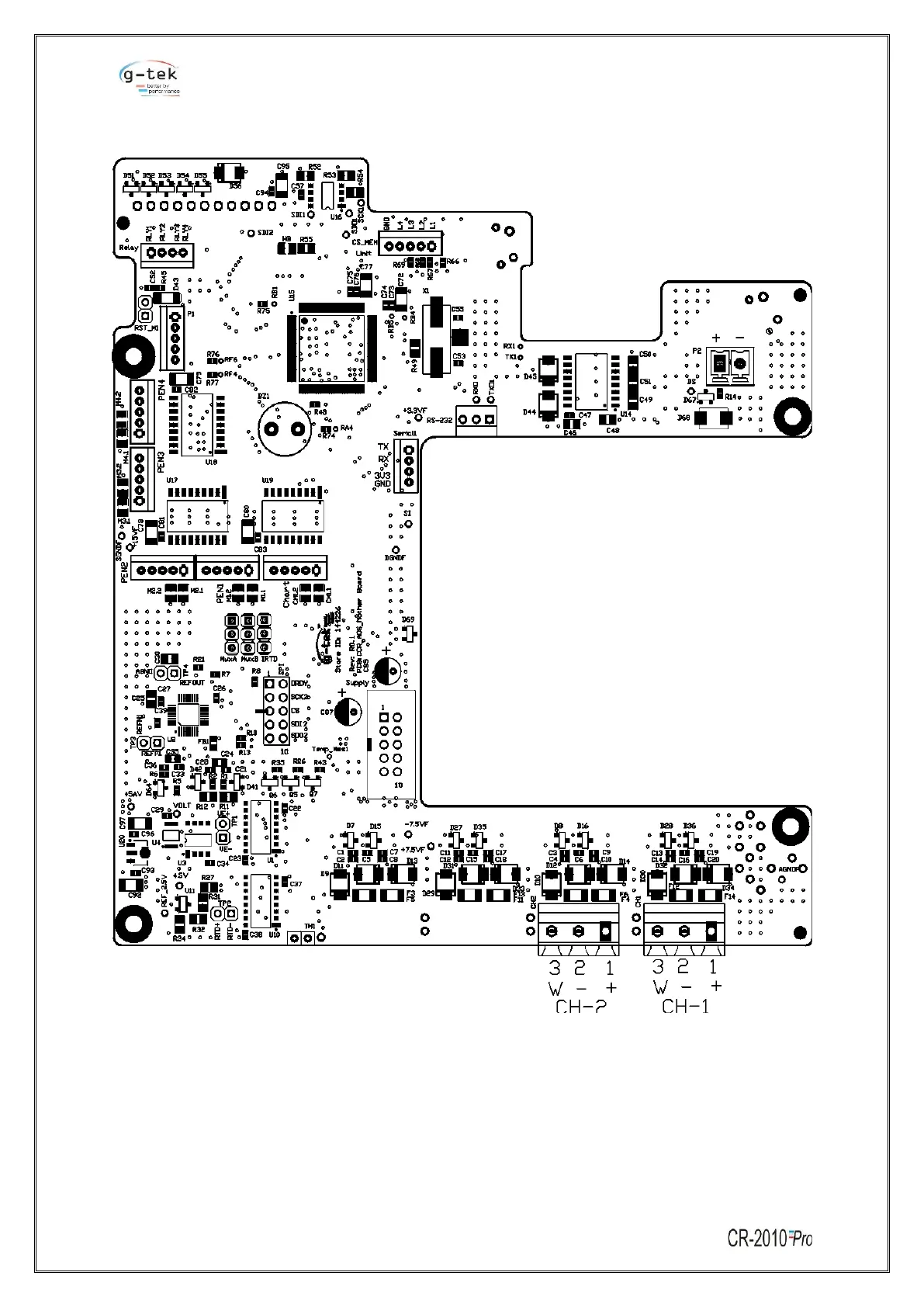
Figure 9 - Motherboard PCB
The Recorder can be connected and configured to operate with a variety of signal sources as
thermocouple, RTDs, dc current, dc voltage etc. The sensor wiring for different sensors for 4 Pen
recorders with display is shown as Table 2
 Loading...