LIST OF FIGURES
Figure 1 - Unpacking and Inspection of Recorder ................................................................................... 6
Figure 2 - Environmental Conditions and Overall Dimensions ............................................................... 7
Figure 3 - Pipe Mounting......................................................................................................................... 8
Figure 4 - Wall Mounting ........................................................................................................................ 8
Figure 5 - Panel Mounting ....................................................................................................................... 9
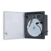
Figure 6 - Opened Chart Plate and Front View of Base Box ................................................................. 13
Figure 7 - Power supply PCB ................................................................................................................. 15
Figure 8 - Sensor Wiring ........................................................................................................................ 17
Figure 9 - Motherboard PCB ................................................................................................................. 18
Figure 10 - Connecting Transmitter with recorder & other instrument using External Power Supply 19
Figure 11 - Connecting Recorder with transmitter using Internal Power Supply ................................. 20
Figure 12 - Fitting / Replacing the Pen .................................................................................................. 21
Figure 13 - Chart Fitting ........................................................................................................................ 22
Figure 14 - Two Pen Recorder Front Panel ........................................................................................... 23
Figure 15 - Main menu display .............................................................................................................. 25
Figure 16 - Chart speed ......................................................................................................................... 26
Figure 17 - Hour/Minute option ........................................................................................................... 26
Figure 18- Display Setting ..................................................................................................................... 27
Figure 19 - Freeze Panel ........................................................................................................................ 27
Figure 20 - Action (Display) ................................................................................................................... 27
Figure 21 - Channel Skip ........................................................................................................................ 28
Figure 22 - CJC ....................................................................................................................................... 29
Figure 23 - Pen Park .............................................................................................................................. 29
Figure 24 - Change Pen ......................................................................................................................... 30
Figure 25 - Channel Configuration ........................................................................................................ 31
Figure 26 - RTD Sensor .......................................................................................................................... 32
Figure 27 - Sensor Selection .................................................................................................................. 34
Figure 28 - Range Low Selection ........................................................................................................... 35
Figure 29 - Span Selection ..................................................................................................................... 35
Figure 30 - Offset Selection ................................................................................................................... 36
Figure 31 - Multiplier Selection ............................................................................................................. 36
Figure 32 - Resolution Decimal Place .................................................................................................... 36
Figure 33 - Alarm Set point High ........................................................................................................... 37
Figure 34 - Alarm Set Point Low ............................................................................................................ 37
Figure 35 - Chart Zero ........................................................................................................................... 38
Figure 36 - Chart Span ........................................................................................................................... 38
Figure 37 - Mechanical calibration ........................................................................................................ 39
Figure 38 - Accessories .......................................................................................................................... 41
 Loading...