The following section describes the operation in a detailed mathematical form, including modeling, analysis and
design.
System Modeling
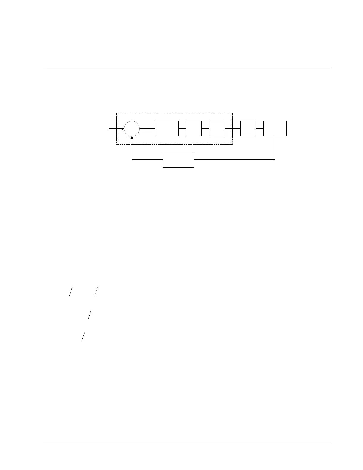
The elements of a servo system include the motor, driver, encoder and the controller. These elements are shown in
Figure 10.4. The mathematical model of the various components is given below.
Figure 10.4: Functional Elements of a Motion Control System
Motor-Amplifier
The motor amplifier may be configured in three modes:
1. Voltage Drive
2. Current Drive
3. Velocity Loop
The operation and modeling in the three modes is as follows:
Voltage Drive
The amplifier is a voltage source with a gain of K
v
[V/V]. The transfer function relating the input voltage, V, to the
motor position, P, is
P V K K S ST ST
V t m e
1 1
where
[s]
and
[s]
and the motor parameters and units are
K
t
Torque constant [Nm/A]
R Armature Resistance Ω
J
Combined inertia of motor and load [kg.m
2
]
L Armature Inductance [H]
When the motor parameters are given in English units, it is necessary to convert the quantities to MKS units. For
example, consider a motor with the parameters:
K
t
= 14.16 oz - in/A = 0.1 Nm/A
R = 2 Ω
Chapter 10 Theory of Operation ▫ 173 DMC-40x0 User Manual
DIGITAL
FILTER
ZOH DAC
ENCODER
AMP MOTOR
CONTROLLER
R
C
X
Y
V E
P

 Loading...

