KDA= 0
KIA= 0
BRA= 0
OE 0
SH A
3. Place a small offset voltage on the motor command line using the OF command (ex OFA= 0.5). The
smallest OF possible to see motion is recommended. If no motion presents itself, increase in small increments
until you see motion. If your OF is beyond what is expected to see motion, record “no motion” using one of
the tables below (Table 2.12 for swapping motor phases or Table 2.13 for swapping halls) and try the next
wiring combination.
Note: To stop the motor from spinning use either the MO A command or issue OFA= 0.
4. Once spinning, check the velocity of the motor with the TV A command. Record this value under “+
Velocity” in either Table 2.12 or Table 2.13.
5. Issue an equal but opposite OF. For example, if you previously issued OFA= 0.5 now issue OFA= -0.5.
Record this velocity under “- Velocity.”
6. Issue OFA= 0 or MO A to stop the motors. Power down the controller and amplifiers system and swap 2
wires of the hall sensors or motor power leads—whichever method is being used (Remember, chose one or
the other, not both!). Keep track of what cable combinations have been tested (labeling the phases maybe
useful) in the example table in Table 2.11, motor phases were recorded based upon their insulation color.
7. Repeat steps 2-6 for every possible wiring combination, there will be six and Table 2.12 or Table 2.13 below
should be completely filled out.
8. The correct wiring combination will be the one with the least difference in magnitude between the
velocities in the positive and negative direction. In the case where there are two combinations that meet this
criteria, choose the combination that has the higher velocities. In the example table shown in Table 2.11, Trial 1
would be the correct choice.
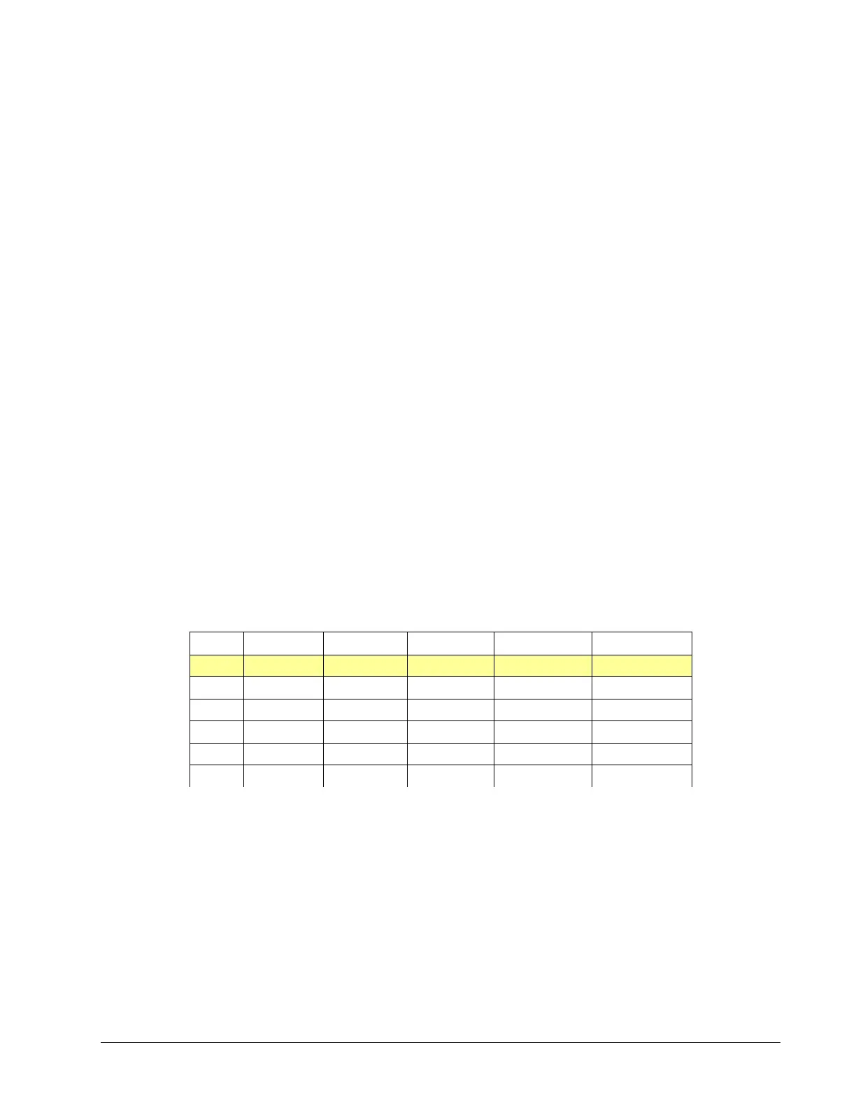
Trial # Phase A Phase B Phase C + Velocity - Velocity
1
Red White Black 153700 -160000
2
Red Black White No motion No motion
3
White Black Red No motion No motion
4
White Red Black -141000 139000
5
Black Red White No motion No motion
6
Black White Red -70000 92000
Table 2.11: Example table showing realistic test results using this commutation method
Chapter 2 Getting Started ▫ 25 DMC-40x0 User Manual

 Loading...

