IC’s and resistor packs in the appropriate sockets. A group of eight LED’s indicates the status of each
I/O point. The numbers above the Bank 0 label indicate the number of the I/O point corresponding to
the LED above it.
Digital Inputs
Configuring a bank for inputs requires that the Ux3 and Ux4 sockets be populated with NEC2505
optical isolation integrated circuits. The IOM-1964 is shipped with a default configuration of banks 2-
7 configured as inputs. The output IC sockets Ux1 and Ux2 must be empty. The input IC’s are labeled
Ux3 and Ux4. For example, in bank 0 the IC’s are U03 and U04, bank 1 input IC’s are labeled U13
and U14, and so on. Also, the resistor pack RPx4 must be inserted into the bank to finish the input
configuration.
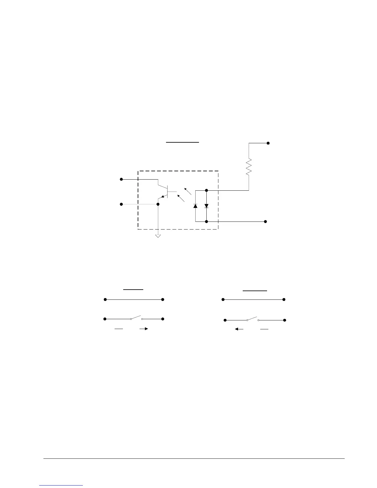
Input Circuit
1/4 NEC2505
To DMC-1748* I/O
DMC-1748* GND
1/8 RPx4
I/OC
n
I/O
n
x = bank number 0-7
n = input number 17-80
Figure A-8
Connections to this optically isolated input circuit are done in a sinking or sourcing configuration,
referring to the direction of current. Some example circuits are shown below:
Sinking
Sourcing
+5V
GND +5V
GNDI/OC
n
I/OC
n
I/O
n
I/O
n
Current
Current
Figure A-9
There is one I/OC connection for each bank of eight inputs. Whether the input is connected as sinking
or souring, when the switch is open no current flows and the digital input function @IN[n] returns 1.
This is because of an internal pull up resistor on the DMC-2x40*. When the switch is closed in either
circuit, current flows. This pulls the input on the DMC-2x40 to ground, and the digital input function
@IN[n] returns 0. Note that the external +5V in the circuits above is for example only. The inputs are
optically isolated and can accept a range of input voltages from 4 to 28 VDC.
Active outputs are connected to the optically isolated inputs in a similar fashion with respect to current.
An NPN output is connected in a sinking configuration, and a PNP output is connected in the sourcing
configuration.
DMC-2X00 Appendices y 223