7. If current is measured using current transformer,
choose the correct current transformer (CT) for the
installation.
WARNING
Make sure that you choose a current transformer (CT)
that is suitable for your installation. Current
transformers of 2 output types can be used. 0-333 mV
or 0 – 5 A output range. For easy installation, GARO
recommends the 0-333 mV type when possible.
0–333 mV is only valid for GARO Entity Balance basic
and 0–5 A is only valid for GARO Entity Balance
ADVANCED. Take notice: 0-5 A output types of current
transformer clamps must never be exposed to open
circuit conditions.
NOTE
This chapter shows the installation of the GARO Entity
Balance basic and the GARO 0-333 mV CT clamps that
are available as accessory. The process for the GARO
Entity Balance advanced is similar.
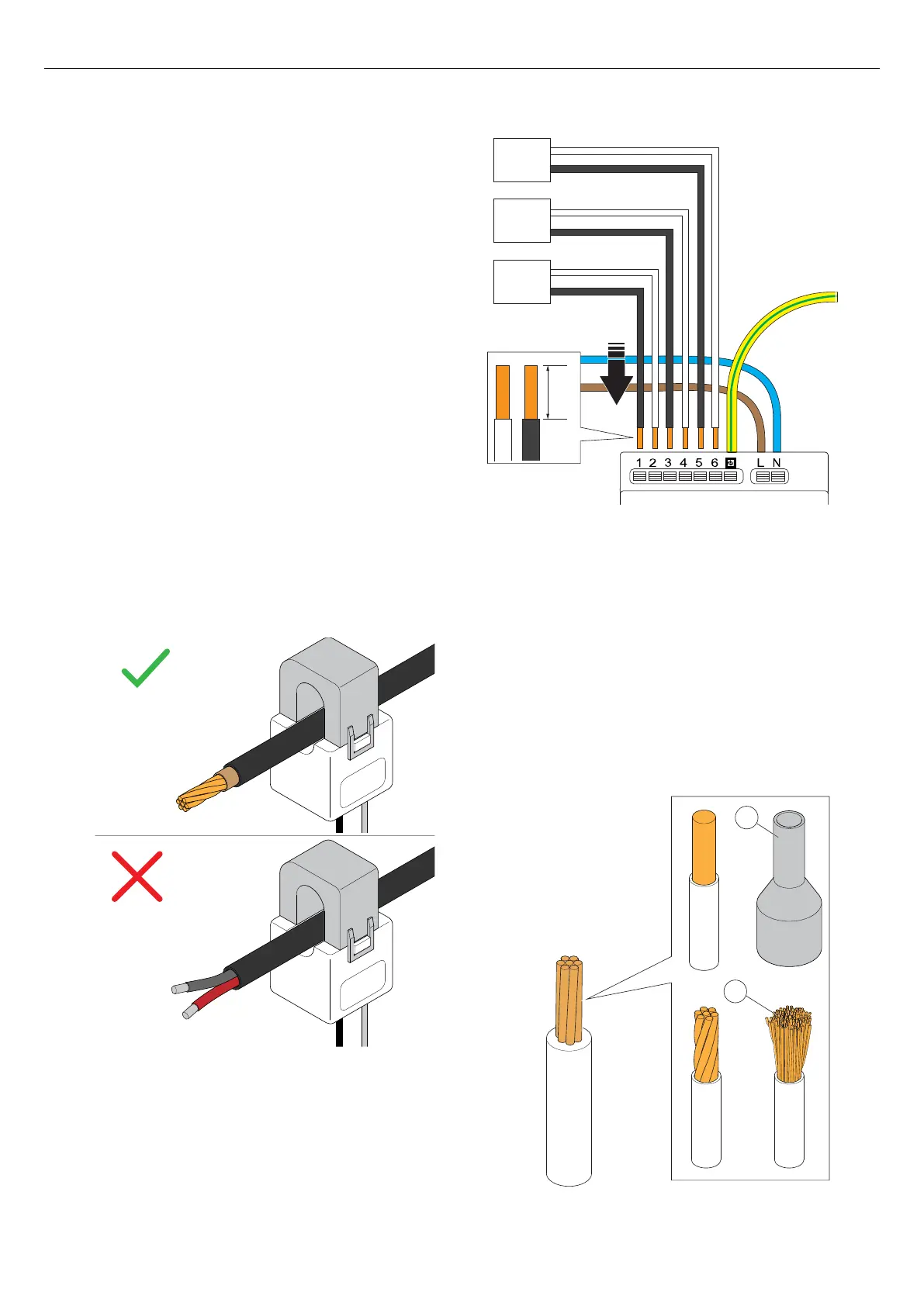
8. Dismantle the current transformer wires and connect
the current transformer clamps to the load interface.
Use a wire ferrule (A) for strained wires (B).
NOTE
The functional grounding connector next to the PE
conductor is internally connected to one of each current
transformer pole (no. 1, 3, 5). This in order to provide a
defined voltage potential. It is recommended that the
functional grounding conductor is connected to a
ground potential, such as the PE conductor.
CT1-3: 0-333 mV (Basic)
CT1-3: 0-5 A (Advanced)
CT3
CT2
CT1
+
-
+
-
+
-
8 mm
CT2-/GND(Black) L
CT1-/GND (Black) L
CT2+ (White) K
CT1+ (White) K
CT3-/GND(Black) L
CT3+ (White) K
A
B
52 Version: 1.3
Installation