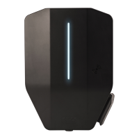
4.11 TO DECIDE THE POSITION OF THE
CHARGING STATION
1. Avoid installing the charging station where snow
(A) can block access to the charging station.
2. Avoid installation in direct sunlight (B) and do not
install the charging station on a hot surface.
3. Make sure that the position of the charging station
is approved from an accessibility (C) perspective.
Comply with local requirements.
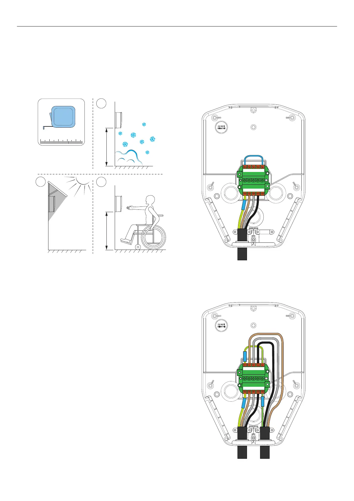
4.12 CABLE INSTALLATION
The GARO Entity is designed to work with both 400 V
TN-S (default) and 230 V IT/TT.
If a 230 V IT system is to be used, the marking of the
installation bracket should be updated, using the
supplied marking stickers.
Once connected, the charging station will detect what
voltage system is uses. The only setting required is
phase connections. Refer to 4.12.5 To connect the
power cable to the terminal, page 31.
As retro-fit, a charging station (CS) may need to be
installed to a 400 V TN-C. However, TN-C is not
recommended and requires that the PEN conductor
area is considered.
- Case 1: Use one side of the installation terminal to
"create" the N, bridge N and PE. Connect PEN to the
PE terminal.
- Case 2: In a daisy-chain connection it is recommended
to use green/yellow tape, blue tape and connect the
PEN according to the picture.
X*
Y*
B
A
C
1234
PE
L1L2L3N
PEL1L2L3N
PE
L1L2L3N
PEL1L2L3N
26 Version: 1.3
Installation