8-
8
750/760 Feeder Management Relay GE Power Management
8.7 DATA LOGGER 8 S1 RELAY SETUP
8
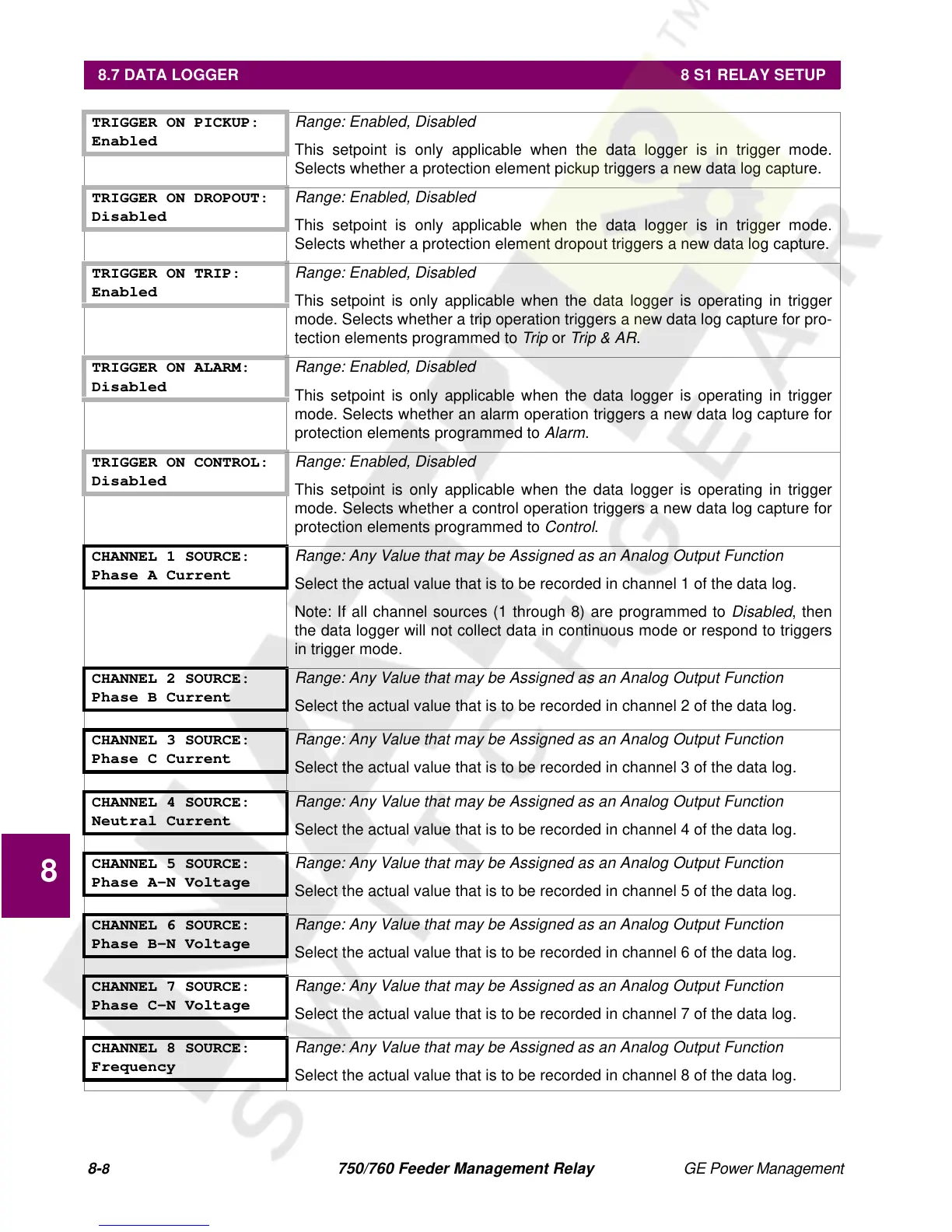
TRIGGER ON PICKUP:
Enabled
Range: Enabled, Disabled
This setpoint is only applicable when the data logger is in trigger mode.
Selects whether a protection element pickup triggers a new data log capture.
TRIGGER ON DROPOUT:
Disabled
Range: Enabled, Disabled
This setpoint is only applicable when the data logger is in trigger mode.
Selects whether a protection element dropout triggers a new data log capture.
TRIGGER ON TRIP:
Enabled
Range: Enabled, Disabled
This setpoint is only applicable when the data logger is operating in trigger
mode. Selects whether a trip operation triggers a new data log capture for pro-
tection elements programmed to
Trip
or
Trip & AR
.
TRIGGER ON ALARM:
Disabled
Range: Enabled, Disabled
This setpoint is only applicable when the data logger is operating in trigger
mode. Selects whether an alarm operation triggers a new data log capture for
protection elements programmed to
Alarm
.
TRIGGER ON CONTROL:
Disabled
Range: Enabled, Disabled
This setpoint is only applicable when the data logger is operating in trigger
mode. Selects whether a control operation triggers a new data log capture for
protection elements programmed to
Control
.
CHANNEL 1 SOURCE:
Phase A Current
Range: Any Value that may be Assigned as an Analog Output Function
Select the actual value that is to be recorded in channel 1 of the data log.
Note: If all channel sources (1 through 8) are programmed to
Disabled
, then
the data logger will not collect data in continuous mode or respond to triggers
in trigger mode.
CHANNEL 2 SOURCE:
Phase B Current
Range: Any Value that may be Assigned as an Analog Output Function
Select the actual value that is to be recorded in channel 2 of the data log.
CHANNEL 3 SOURCE:
Phase C Current
Range: Any Value that may be Assigned as an Analog Output Function
Select the actual value that is to be recorded in channel 3 of the data log.
CHANNEL 4 SOURCE:
Neutral Current
Range: Any Value that may be Assigned as an Analog Output Function
Select the actual value that is to be recorded in channel 4 of the data log.
CHANNEL 5 SOURCE:
Phase A-N Voltage
Range: Any Value that may be Assigned as an Analog Output Function
Select the actual value that is to be recorded in channel 5 of the data log.
CHANNEL 6 SOURCE:
Phase B-N Voltage
Range: Any Value that may be Assigned as an Analog Output Function
Select the actual value that is to be recorded in channel 6 of the data log.
CHANNEL 7 SOURCE:
Phase C-N Voltage
Range: Any Value that may be Assigned as an Analog Output Function
Select the actual value that is to be recorded in channel 7 of the data log.
CHANNEL 8 SOURCE:
Frequency
Range: Any Value that may be Assigned as an Analog Output Function
Select the actual value that is to be recorded in channel 8 of the data log.

 Loading...


