12-
62
750/760 Feeder Management Relay GE Power Management
12.9 BREAKER FAILURE 12 S5 PROTECTION
12
12.9 BREAKER FAILURE 12.9.1 DESCRIPTION
Breaker failure monitors the phase currents while a trip command exists. If any phase current is above the set
level after the
BREAKER FAILURE DELAY
time expires, a breaker failure will be declared, which will operate the
selected output relays and force the 760 autoreclose scheme to lockout.
To provide user flexibility, the 750/760 has included two programmable delays for the
BREAKER FAILURE FUNC-
TION
. The timers can be used singularly or in combination with each other. The difference between the two is
their location in the logic diagram. Delay 1 starts counting down from the user programmed delay setpoint once
a Trip condition is recognized. On the other hand, Delay 2 provides a delay where it does not begin counting
down until a trip condition is present, Delay 1 has expired, and one of the phase currents is above the
BREAKER
FAILURE CURRENT
setpoint. If one of the delays is not required, simply program the unwanted timer to its mini-
mum value.
12.9.2 SETTINGS
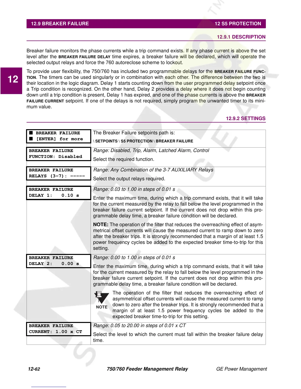
■ BREAKER FAILURE
■ [ENTER] for more
The Breaker Failure setpoints path is:
\ SETPOINTS \ S5 PROTECTION \ BREAKER FAILURE
BREAKER FAILURE
FUNCTION: Disabled
Range: Disabled, Trip, Alarm, Latched Alarm, Control
Select the required function.
BREAKER FAILURE
RELAYS (3-7): -----
Range: Any Combination of the 3-7 AUXILIARY Relays
Select the output relays required.
BREAKER FAILURE
DELAY 1: 0.10 s
Range: 0.03 to 1.00 in steps of 0.01 s
Enter the maximum time, during which a trip command exists, that it will take
for the current measured by the relay to fall below the level programmed in the
breaker failure current setpoint. If the current does not drop within this pro-
grammable delay time, a breaker failure condition will be declared.
NOTE:
The operation of the filter that reduces the overreaching effect of asym-
metrical offset currents will cause the measured current to ramp down to zero
after the breaker trips. It is strongly recommended that a margin of at least 1.5
power frequency cycles be added to the expected breaker time-to-trip for this
setting.
BREAKER FAILURE
DELAY 2: 0.00 s
Range: 0.00 to 1.00 in steps of 0.01 s
Enter the maximum time, during which a trip command exists, that it will take
for the current measured by the relay to fall below the level programmed in the
breaker failure current setpoint. If the current does not drop within this pro-
grammable delay time, a breaker failure condition will be declared.
The operation of the filter that reduces the overreaching effect of
asymmetrical offset currents will cause the measured current to ramp
down to zero after the breaker trips. It is strongly recommended that a
margin of at least 1.5 power frequency cycles be added to the
expected breaker time-to-trip for this setting.
BREAKER FAILURE
CURRENT: 1.00 x CT
Range: 0.05 to 20.00 in steps of 0.01 x CT
Select the level to which the current must fall within the breaker failure delay
time.
NOTE

 Loading...


