13-
8
750/760 Feeder Management Relay GE Power Management
13.3 FAULT LOCATOR 13 S6 MONITORING
13
13.3.2 SETPOINTS
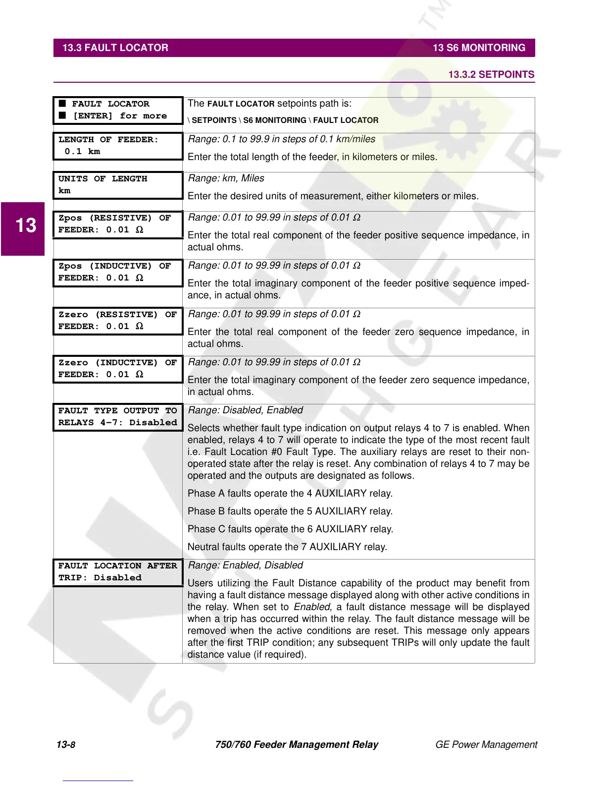
■ FAULT LOCATOR
■ [ENTER] for more
The
FAULT LOCATOR
setpoints path is:
\ SETPOINTS \ S6 MONITORING \ FAULT LOCATOR
LENGTH OF FEEDER:
0.1 km
Range: 0.1 to 99.9 in steps of 0.1 km/miles
Enter the total length of the feeder, in kilometers or miles.
UNITS OF LENGTH
km
Range: km, Miles
Enter the desired units of measurement, either kilometers or miles.
Zpos (RESISTIVE) OF
FEEDER: 0.01
Ω
Range: 0.01 to 99.99 in steps of 0.01
Ω
Enter the total real component of the feeder positive sequence impedance, in
actual ohms.
Zpos (INDUCTIVE) OF
FEEDER: 0.01
Ω
Range: 0.01 to 99.99 in steps of 0.01
Ω
Enter the total imaginary component of the feeder positive sequence imped-
ance, in actual ohms.
Zzero (RESISTIVE) OF
FEEDER: 0.01
Ω
Range: 0.01 to 99.99 in steps of 0.01
Ω
Enter the total real component of the feeder zero sequence impedance, in
actual ohms.
Zzero (INDUCTIVE) OF
FEEDER: 0.01
Ω
Range: 0.01 to 99.99 in steps of 0.01
Ω
Enter the total imaginary component of the feeder zero sequence impedance,
in actual ohms.
FAULT TYPE OUTPUT TO
RELAYS 4-7: Disabled
Range: Disabled, Enabled
Selects whether fault type indication on output relays 4 to 7 is enabled. When
enabled, relays 4 to 7 will operate to indicate the type of the most recent fault
i.e. Fault Location #0 Fault Type. The auxiliary relays are reset to their non-
operated state after the relay is reset. Any combination of relays 4 to 7 may be
operated and the outputs are designated as follows.
Phase A faults operate the 4 AUXILIARY relay.
Phase B faults operate the 5 AUXILIARY relay.
Phase C faults operate the 6 AUXILIARY relay.
Neutral faults operate the 7 AUXILIARY relay.
FAULT LOCATION AFTER
TRIP: Disabled
Range: Enabled, Disabled
Users utilizing the Fault Distance capability of the product may benefit from
having a fault distance message displayed along with other active conditions in
the relay. When set to
Enabled
, a fault distance message will be displayed
when a trip has occurred within the relay. The fault distance message will be
removed when the active conditions are reset. This message only appears
after the first TRIP condition; any subsequent TRIPs will only update the fault
distance value (if required).

 Loading...


