GE Power Management 750/760 Feeder Management Relay 17-
17
17 COMMISSIONING 17.6 METERING
17
17.6.7 MEASUREMENT OF CURRENT DEMAND
Test Connections per Figure 17–1: RELAY TEST WIRING – WYE CONNECTION or Figure 17–2: RELAY
TEST WIRING – DELTA CONNECTION on page 17–4.
Expected Accuracy:
± 2.0% of full scale
To reset the "Last Demand" reading to 0 between tests, cycle the relay power source off/on.
Block Interval and Rolling demand measurement types must be tested in synchronization with the internal
clock. Both of these measurements start with the first interval of the day at 12:00:00.000 midnight. To synchro-
nize, preset the injection levels, then turn the current off. Select the relay display (not the 750/760PC program)
to
A1 STATUS \ CLOCK \ CURRENT TIME
. Apply the test current when the clock is at the beginning of an interval
measurement period, as determined by the
TIME INTERVAL
setpoint for the element.
Actual Values Displays:
Under subheading
A2 METERING \ DEMAND \ PHASE A CURRENT \
LAST PHASE A CURRENT DEMAND
MAX PHASE A CURRENT DEMAND
(DATE, TIME)
Under subheading
A2 METERING \ DEMAND \ PHASE B CURRENT \
LAST PHASE B CURRENT DEMAND
MAX PHASE B CURRENT DEMAND (DATE, TIME)
Under subheading
A2 METERING \ DEMAND \ PHASE C CURRENT \
LAST PHASE C CURRENT DEMAND
MAX PHASE C CURRENT DEMAND (DATE, TIME)
Procedure:
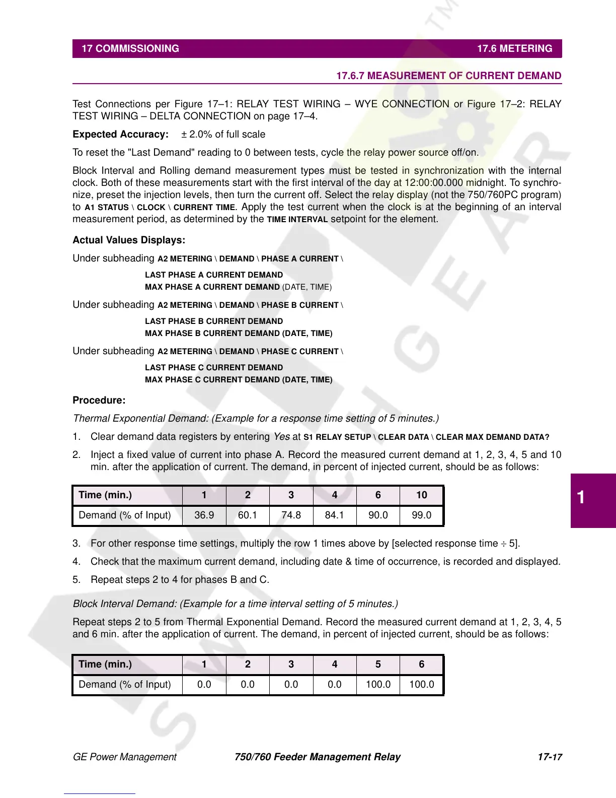
Thermal Exponential Demand: (Example for a response time setting of 5 minutes.)
1. Clear demand data registers by entering
Yes
at
S1 RELAY SETUP \ CLEAR DATA \ CLEAR MAX DEMAND DATA?
2. Inject a fixed value of current into phase A. Record the measured current demand at 1, 2, 3, 4, 5 and 10
min. after the application of current. The demand, in percent of injected current, should be as follows:
3. For other response time settings, multiply the row 1 times above by [selected response time
÷
5].
4. Check that the maximum current demand, including date & time of occurrence, is recorded and displayed.
5. Repeat steps 2 to 4 for phases B and C.
Block Interval Demand: (Example for a time interval setting of 5 minutes.)
Repeat steps 2 to 5 from Thermal Exponential Demand. Record the measured current demand at 1, 2, 3, 4, 5
and 6 min. after the application of current. The demand, in percent of injected current, should be as follows:
Time (min.) 1 2 3 4 6 10
Demand (% of Input) 36.9 60.1 74.8 84.1 90.0 99.0
Time (min.) 1 2 3 4 5 6
Demand (% of Input) 0.0 0.0 0.0 0.0 100.0 100.0

 Loading...


