GE Power Management 750/760 Feeder Management Relay 9-
3
9 S2 SYSTEM SETUP 9.3 LINE VT SENSING
9
9.3 LINE VT SENSING 9.3.1 DESCRIPTION
With a line VT installed, the relay can be used to check for a condition of synchronism between two voltages,
either line-line or line-neutral.
9.3.2 SETTINGS
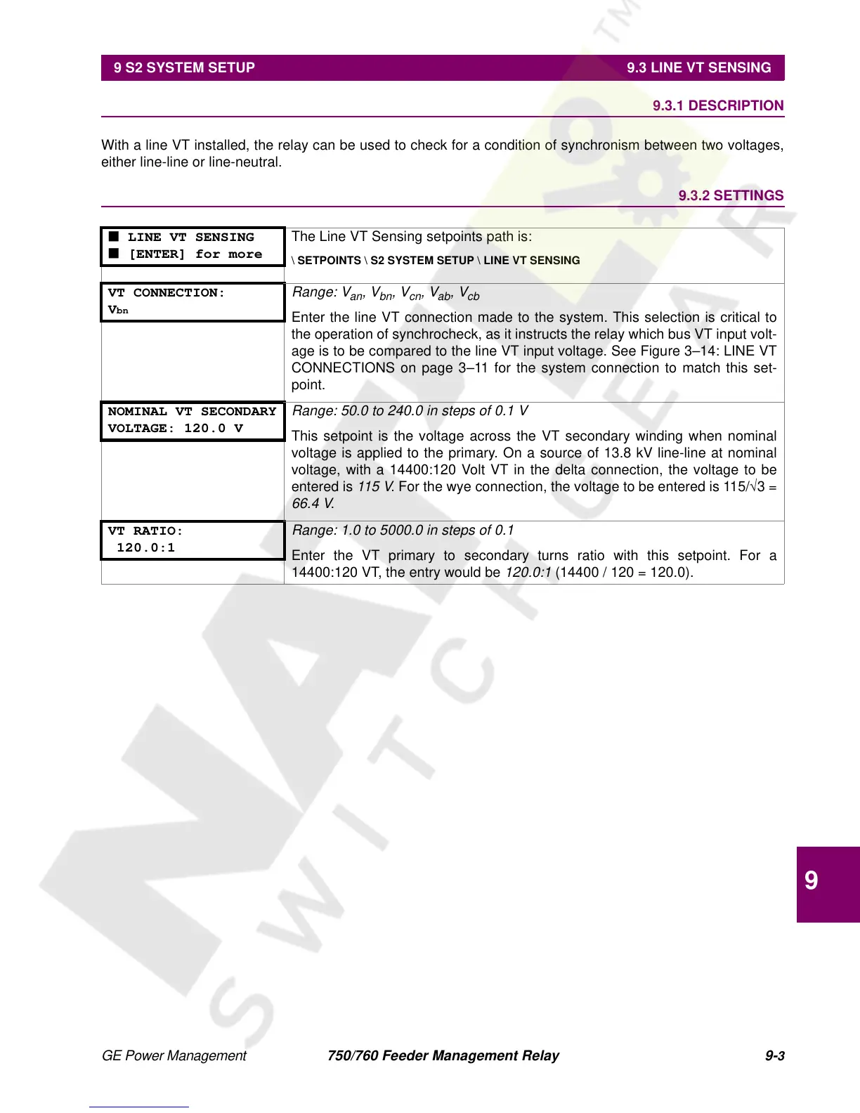
■ LINE VT SENSING
■ [ENTER] for more
The Line VT Sensing setpoints path is:
\ SETPOINTS \ S2 SYSTEM SETUP \ LINE VT SENSING
VT CONNECTION:
V
bn
Range: V
an
, V
bn
, V
cn
, V
ab
, V
cb
Enter the line VT connection made to the system. This selection is critical to
the operation of synchrocheck, as it instructs the relay which bus VT input volt-
age is to be compared to the line VT input voltage. See Figure 3–14: LINE VT
CONNECTIONS on page 3–11 for the system connection to match this set-
point.
NOMINAL VT SECONDARY
VOLTAGE: 120.0 V
Range: 50.0 to 240.0 in steps of 0.1 V
This setpoint is the voltage across the VT secondary winding when nominal
voltage is applied to the primary. On a source of 13.8 kV line-line at nominal
voltage, with a 14400:120 Volt VT in the delta connection, the voltage to be
entered is
115 V
. For the wye connection, the voltage to be entered is 115/
√
3 =
66.4 V
.
VT RATIO:
120.0:1
Range: 1.0 to 5000.0 in steps of 0.1
Enter the VT primary to secondary turns ratio with this setpoint. For a
14400:120 VT, the entry would be
120.0:1
(14400 / 120 = 120.0).

 Loading...


