17-
44
750/760 Feeder Management Relay GE Power Management
17.8 MONITORING 17 COMMISSIONING
17
17.8.3 FAULT LOCATOR
Test Connections per Figure 17–1: RELAY TEST WIRING – WYE CONNECTION or Figure 17–2: RELAY
TEST WIRING – DELTA CONNECTION on page 17–4.
Because of the broad range of variables that can be encountered in actual systems a represen-
tative configuration with a set of impedances and instrument transformers have been chosen
to demonstrate these tests. The model used to calculate the voltage and current phasors for
the tests is a radial, 10 km long, three phase, four wire system of 13.8 kV nominal and 600 amp
feeder capacity. At the relay location there are wye-connected VTs rated 14400/120 V and CTs
rated 600/5 A. A prefault load of about 8.5 MVA exists on the feeder. The relay is a 5 Amp unit.
The source voltage (ahead of the source impedance) is 14.0 kV
∠
1.6°. Any overcurrent feature, all of which can
cause a fault location calculation by tripping, set to a pickup current below the programmed test current, can be
used for the tests.
Procedure:
1. Program the test set with the following
prefault
voltages and currents.
V
an
= 67.8
∠
0°;
V
bn
= 67.8
∠
240°;
V
cn
= 67.8
∠
120°;
I
a
= 2.9
∠
330°;
I
b
= 2.9
∠
210°;
I
c
= 2.9
∠
90°
2. Program the test set with the following fault voltages and currents.
V
an
= 59.0
∠
0°;
V
bn
= 67.4
∠
241°;
V
cn
= 67.4
∠
121°;
I
a
= 13.0
∠
286°;
I
b
= 2.9
∠
210°;
I
c
= 2.9
∠
90°
This fault is from phase A to ground, placed 5.0 km from the relay.
3. Inject the prefault voltages and currents, then apply the fault. The relay should trip and determine the type
of fault (A-G), the distance to the fault (5.0 km) and the reactance to the fault (2.73
Ω
).
4. Program the test set with the following fault voltages and currents.
V
an
= 67.4
∠
2°;
V
bn
= 60.3
∠
242°;
V
cn
= 67.4
∠
122°;
I
a
= 2.9
∠
330°;
I
b
= 12.0
∠
166°;
I
c
= 2.9
∠
90°
This fault is phase B to ground, placed 6.0 km from the relay.
5. Inject the prefault voltages and currents, then apply the fault. The relay should trip and determine the type
of fault (B-G), the distance to the fault (6.0 km) and the reactance to the fault (3.27
Ω
).
6. Program the test set with the following fault voltages and currents.
V
an
= 67.4
∠
2°;
V
bn
= 67.4
∠
242°;
V
cn
= 61.3
∠
120°;
I
a
= 2.9
∠
330°;
I
b
= 2.9
∠
210°;
I
c
= 9.9
∠
47°
This fault is phase C to ground, placed 7.0 km from the relay.
7. Inject the prefault voltages and currents, then apply the fault. The relay should trip and determine the type
of fault (C-G), the distance to the fault (7.0 km) and the reactance to the fault (3.82
Ω
).
8. Program the test set with the following fault voltages and currents.
V
an
= 60.4
∠
4°;
V
bn
= 67.4
∠
242°;
V
cn
= 61.7
∠
117°;
I
a
= 11.4
∠
253°;
I
b
= 2.9
∠
210°;
I
c
= 11.4
∠
73°
This fault is phase A to C, placed 8.0 km from the relay.
9. Inject the prefault voltages and currents, then apply the fault parameters. The relay should trip and deter-
mine the type of fault (A-C), the distance to the fault (8.0 km) and the reactance to the fault (4.36
Ω
).
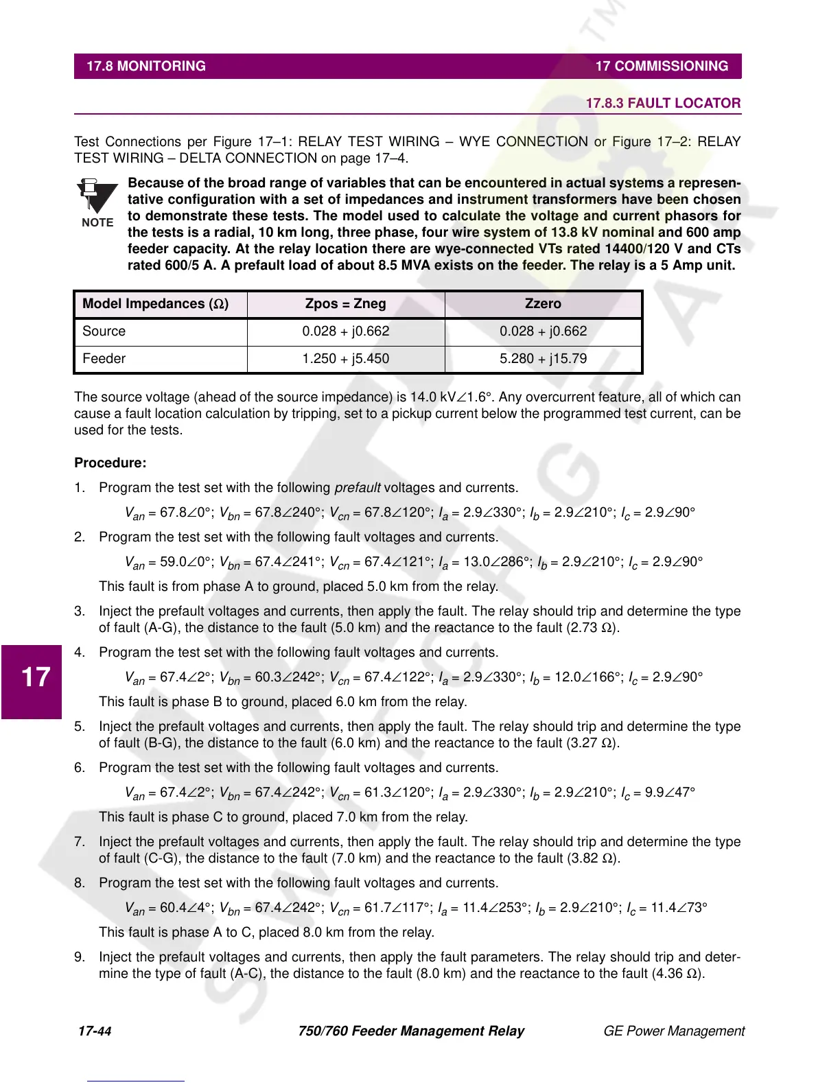
Model Impedances (
Ω
) Zpos = Zneg Zzero
Source 0.028 + j0.662 0.028 + j0.662
Feeder 1.250 + j5.450 5.280 + j15.79
NOTE

 Loading...


