3-
12
750/760 Feeder Management Relay GE Power Management
3.2 TYPICAL WIRING 3 INSTALLATION
3
If delta VTs are used, zero sequence voltage (
V
o
) and neutral/sensitive ground polarizing voltage (–
V
o
) will be zero. Also with this delta VT connection, the phase-neutral voltage cannot be measured
and will not be displayed.
The single phase input is designated as the “line voltage”. The line VT input channel, used for the
synchrocheck feature, can be connected for phase-neutral voltages
V
an
,
V
bn
, or
V
cn
; or for phase-phase volt-
ages
V
ab
or
V
cb
as shown below.
3.2.10 CONTROL POWER
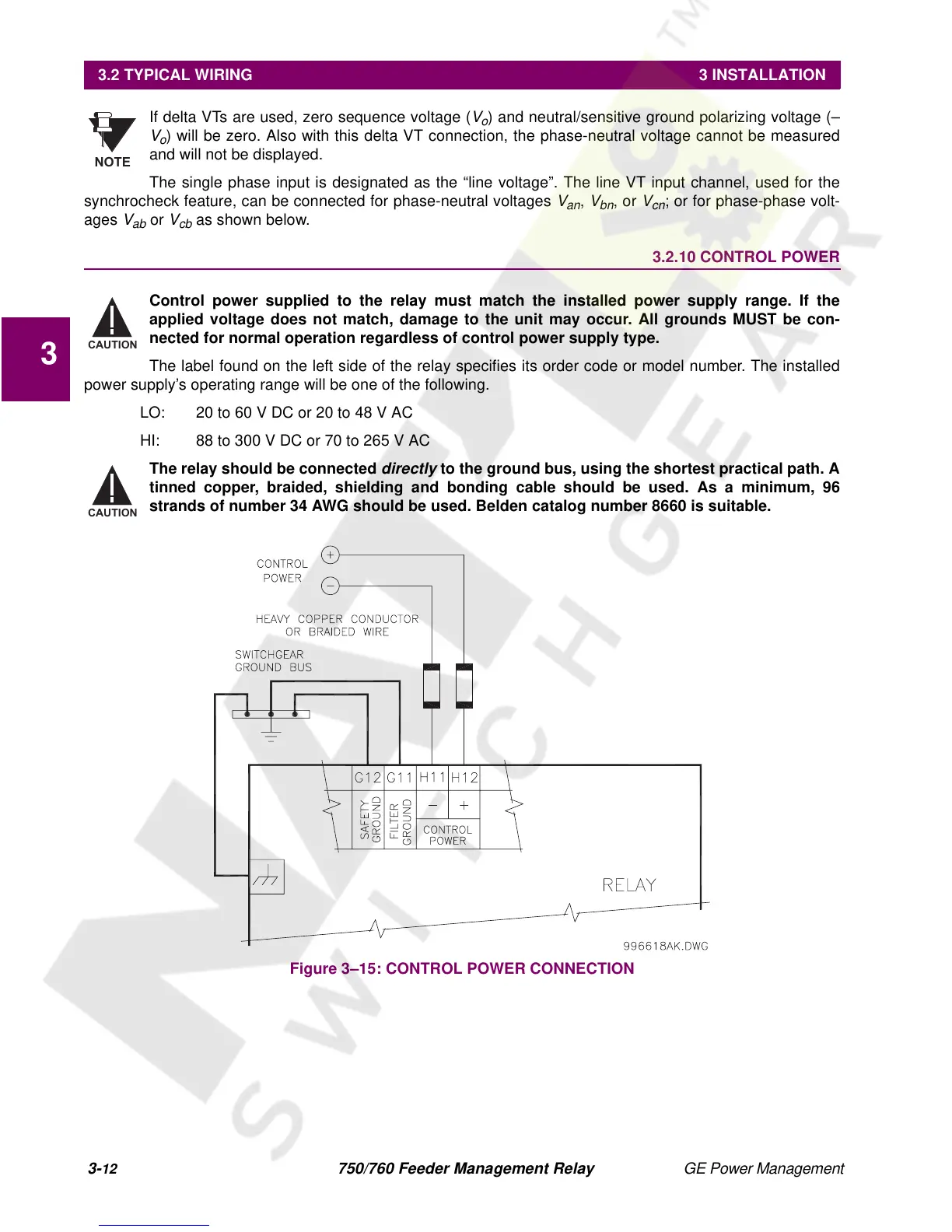
Control power supplied to the relay must match the installed power supply range. If the
applied voltage does not match, damage to the unit may occur. All grounds MUST be con-
nected for normal operation regardless of control power supply type.
The label found on the left side of the relay specifies its order code or model number. The installed
power supply’s operating range will be one of the following.
LO: 20 to 60 V DC or 20 to 48 V AC
HI: 88 to 300 V DC or 70 to 265 V AC
The relay should be connected
directly
to the ground bus, using the shortest practical path. A
tinned copper, braided, shielding and bonding cable should be used. As a minimum, 96
strands of number 34 AWG should be used. Belden catalog number 8660 is suitable.
Figure 3–15: CONTROL POWER CONNECTION
NOTE
CAUTION
CAUTION

 Loading...


