GE Power Management 750/760 Feeder Management Relay 3-
3
3 INSTALLATION 3.1 DRAWOUT CASE
3
3.1.3 UNIT WITHDRAWAL AND INSERTION
TURN OFF CONTROL POWER BEFORE DRAWING OUT OR RE-INSERTING THE RELAY TO
PREVENT MALOPERATION!
If an attempt is made to install a relay into a non-matching case, the case’s configuration pin
will prevent full insertion. Applying a strong force in this instance will result in damage to the
relay and case.
To remove the unit from the case:
1. Open the door by pulling from the top or bottom of its right side. It will rotate to the left about its hinges.
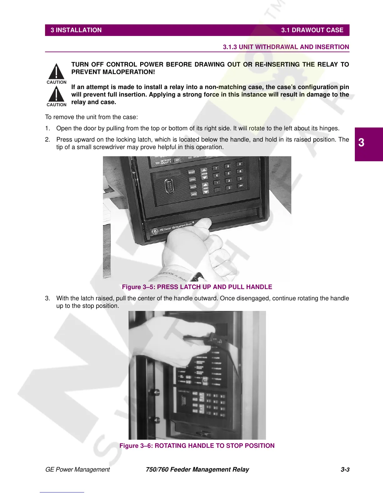
2. Press upward on the locking latch, which is located below the handle, and hold in its raised position. The
tip of a small screwdriver may prove helpful in this operation.
Figure 3–5: PRESS LATCH UP AND PULL HANDLE
3. With the latch raised, pull the center of the handle outward. Once disengaged, continue rotating the handle
up to the stop position.
Figure 3–6: ROTATING HANDLE TO STOP POSITION
CAUTION
CAUTION

 Loading...


