3-
4
750/760 Feeder Management Relay GE Power Management
3.1 DRAWOUT CASE 3 INSTALLATION
3
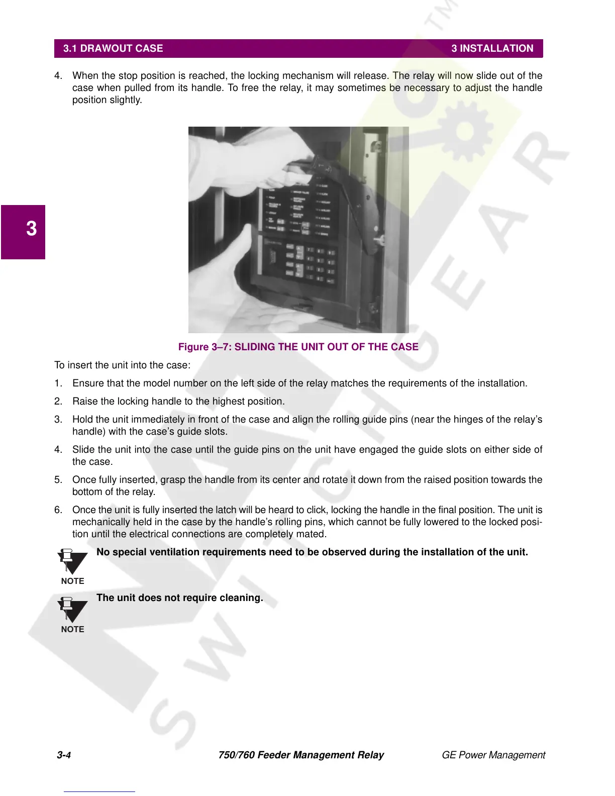
4. When the stop position is reached, the locking mechanism will release. The relay will now slide out of the
case when pulled from its handle. To free the relay, it may sometimes be necessary to adjust the handle
position slightly.
Figure 3–7: SLIDING THE UNIT OUT OF THE CASE
To insert the unit into the case:
1. Ensure that the model number on the left side of the relay matches the requirements of the installation.
2. Raise the locking handle to the highest position.
3. Hold the unit immediately in front of the case and align the rolling guide pins (near the hinges of the relay’s
handle) with the case’s guide slots.
4. Slide the unit into the case until the guide pins on the unit have engaged the guide slots on either side of
the case.
5. Once fully inserted, grasp the handle from its center and rotate it down from the raised position towards the
bottom of the relay.
6. Once the unit is fully inserted the latch will be heard to click, locking the handle in the final position. The unit is
mechanically held in the case by the handle’s rolling pins, which cannot be fully lowered to the locked posi-
tion until the electrical connections are completely mated.
No special ventilation requirements need to be observed during the installation of the unit.
The unit does not require cleaning.
NOTE
NOTE

 Loading...


