12-
20
750/760 Feeder Management Relay GE Power Management
12.3 NEUTRAL OVERCURRENT 12 S5 PROTECTION
12
12.3.4 NEUTRAL DIRECTIONAL
The neutral directional feature controls the operation of all neutral overcurrent elements and allows them to
discriminate between forward or reverse faults. Refer to Section 12.2: DIRECTIONAL OVERCURRENT
CHARACTERISTICS on page 12–6 for more details on directional principles. Neutral directional can be either
voltage, current, or dual polarized. The calculated neutral current is always the operating current.
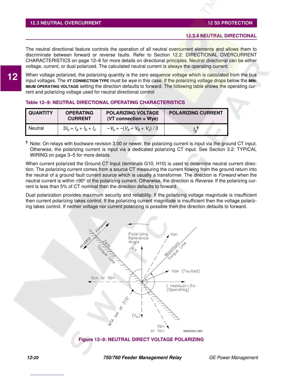
When voltage polarized, the polarizing quantity is the zero sequence voltage which is calculated from the bus
input voltages. The
VT CONNECTION TYPE
must be
wye
in this case. If the polarizing voltage drops below the
MIN-
IMUM OPERATING VOLTAGE
setting the direction defaults to forward. The following table shows the operating cur-
rent and polarizing voltage used for neutral directional control
†
Note: On relays with bootware revision 3.00 or newer, the polarizing current is input via the ground CT input.
Otherwise, the polarizing current is input via a dedicated polarizing CT input. See Section 3.2: TYPICAL
WIRING on page 3–5 for more details.
When current polarized the Ground CT Input (terminals G10, H10) is used to determine neutral current direc-
tion. The polarizing current comes from a source CT measuring the current flowing from the ground return into
the neutral of a ground fault current source which is usually a transformer. The direction is
Forward
when the
neutral current is within
±
90
°
of the polarizing current. Otherwise, the direction is
Reverse
. If the polarizing cur-
rent is less than 5% of CT nominal then the direction defaults to forward.
Dual polarization provides maximum security and reliability. If the polarizing voltage magnitude is insufficient
then current polarizing takes control. If the polarizing current magnitude is insufficient then the voltage polariz-
ing takes control. If neither voltage nor current polarizing is possible then the direction defaults to forward.
Figure 12–9: NEUTRAL DIRECT VOLTAGE POLARIZING
Table 12–9: NEUTRAL DIRECTIONAL OPERATING CHARACTERISTICS
QUANTITY OPERATING
CURRENT
POLARIZING VOLTAGE
(VT connection = Wye)
POLARIZING CURRENT
Neutral 3
I
o
=
I
a
+
I
b
+
I
c
–
V
o
= –(
V
a
+
V
b
+
V
c
) / 3
I
g
†

 Loading...


