GE Power Management 750/760 Feeder Management Relay 17-
11
17 COMMISSIONING 17.5 OUTPUT RELAYS
17
17.5 OUTPUT RELAYS 17.5.1 INDICATORS
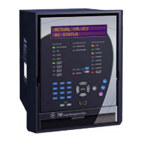
Front panel OUTPUT STATUS indicators.
17.5.2 PROCEDURE
1. Enter settings under subheading
S8 TESTING \ OUTPUT RELAYS \
FORCE OUTPUT RELAYS FUNCTION:
Enabled
FORCE 1 TRIP RELAY:
De-energized
FORCE 2 CLOSE RELAY:
De-energized
FORCE 3 AUXILIARY RELAY:
De-energized
FORCE 4 AUXILIARY RELAY:
De-energized
FORCE 5 AUXILIARY RELAY:
De-energized
FORCE 6 AUXILIARY RELAY:
De-energized
FORCE 7 AUXILIARY RELAY:
De-energized
FORCE 8 SELF-TEST RELAY:
De-energized
FORCE SOLID STATE OUTPUT:
De-energized
2. Using a multimeter, check that all output relays are de-energized (i.e. N.O. contacts are open, N.C. con-
tacts are closed).
3. Change setting to:
S8 TESTING \ OUTPUT RELAYS \ FORCE 1 TRIP RELAY
:
Energized
4. Check that the 1 TRIP output is energized (i.e. N.O. contacts are closed), and the 1 TRIP indicator on the
faceplate is illuminated.
5. Change setting to:
S8 TESTING \ OUTPUT RELAYS \ FORCE 1 TRIP RELAY
:
De-Energized
6. Repeat steps 3 through 5 for output relays 2 through 8 inclusive.
7. Observing polarity, connect a DC source of a minimum of 5 volt, in series with a limiting resistor that will
permit a minimum current of 100 mA, in series with the Solid State output. Observing polarity, connect a
DC voltmeter across the limiting resistor. Check there is no voltage displayed on the voltmeter.
8. Change setting to:
S8 TESTING \ OUTPUT RELAYS \ FORCE SOLID STATE OUTPUT
:
Energized
9. Check that a voltage has appeared on the voltmeter. Turn off the source and disconnect the test wiring.
10. Change setting to:
S8 TESTING \ OUTPUT RELAYS \ FORCE SOLID STATE OUTPUT
:
De-Energized
11. Change setting to:
S8 TESTING \ OUTPUT RELAYS \ FORCE OUTPUT RELAYS FUNCTION
:
Disabled

 Loading...