GE Power Management
750/760 Feeder Management Relay 14-
7
14 S7 CONTROL 14.2 SYNCHROCHECK
14
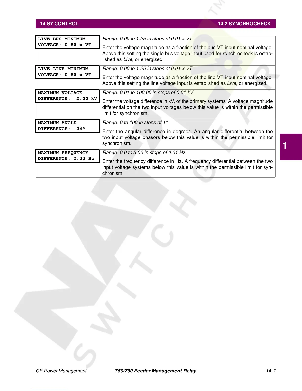
LIVE BUS MINIMUM
VOLTAGE: 0.80 x VT
Range: 0.00 to 1.25 in steps of 0.01 x VT
Enter the voltage magnitude as a fraction of the bus VT input nominal voltage.
Above this setting the single bus voltage input used for synchrocheck is estab-
lished as
Live
, or energized.
LIVE LINE MINIMUM
VOLTAGE: 0.80 x VT
Range: 0.00 to 1.25 in steps of 0.01 x VT
Enter the voltage magnitude as a fraction of the line VT input nominal voltage.
Above this setting the line voltage input is established as
Live
, or energized.
MAXIMUM VOLTAGE
DIFFERENCE: 2.00 kV
Range: 0.01 to 100.00 in steps of 0.01 kV
Enter the voltage difference in kV, of the primary systems. A voltage magnitude
differential on the two input voltages below this value is within the permissible
limit for synchronism.
MAXIMUM ANGLE
DIFFERENCE: 24°
Range: 0 to 100 in steps of 1°
Enter the angular difference in degrees. An angular differential between the
two input voltage phasors below this value is within the permissible limit for
synchronism.
MAXIMUM FREQUENCY
DIFFERENCE: 2.00 Hz
Range: 0.0 to 5.00 in steps of 0.01 Hz
Enter the frequency difference in Hz. A frequency differential between the two
input voltage systems below this value is within the permissible limit for syn-
chronism.

 Loading...


