16-
52
750/760 Feeder Management Relay GE Power Management
16.4 MODBUS MEMORY MAP 16 COMMUNICATIONS
16
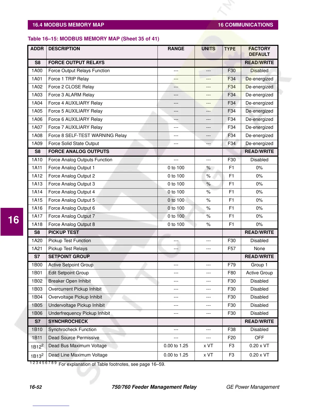
S8 FORCE OUTPUT RELAYS READ/WRITE
1A00 Force Output Relays Function --- --- F30 Disabled
1A01 Force 1 TRIP Relay --- --- F34 De-energized
1A02 Force 2 CLOSE Relay --- --- F34 De-energized
1A03 Force 3 ALARM Relay --- --- F34 De-energized
1A04 Force 4 AUXILIARY Relay --- --- F34 De-energized
1A05 Force 5 AUXILIARY Relay --- --- F34 De-energized
1A06 Force 6 AUXILIARY Relay --- --- F34 De-energized
1A07 Force 7 AUXILIARY Relay --- --- F34 De-energized
1A08 Force 8 SELF-TEST WARNING Relay --- --- F34 De-energized
1A09 Force Solid State Output --- --- F34 De-energized
S8 FORCE ANALOG OUTPUTS READ/WRITE
1A10 Force Analog Outputs Function --- --- F30 Disabled
1A11 Force Analog Output 1 0 to 100 % F1 0%
1A12 Force Analog Output 2 0 to 100 % F1 0%
1A13 Force Analog Output 3 0 to 100 % F1 0%
1A14 Force Analog Output 4 0 to 100 % F1 0%
1A15 Force Analog Output 5 0 to 100 % F1 0%
1A16 Force Analog Output 6 0 to 100 % F1 0%
1A17 Force Analog Output 7 0 to 100 % F1 0%
1A18 Force Analog Output 8 0 to 100 % F1 0%
S8 PICKUP TEST READ/WRITE
1A20 Pickup Test Function --- --- F30 Disabled
1A21 Pickup Test Relays --- --- F57 None
S7 SETPOINT GROUP READ/WRITE
1B00 Active Setpoint Group --- --- F79 Group 1
1B01 Edit Setpoint Group --- --- F80 Active Group
1B02 Breaker Open Inhibit --- --- F30 Disabled
1B03 Overcurrent Pickup Inhibit --- --- F30 Disabled
1B04 Overvoltage Pickup Inhibit --- --- F30 Disabled
1B05 Undervoltage Pickup Inhibit --- --- F30 Disabled
1B06 Underfrequency Pickup Inhibit --- --- F30 Disabled
S7 SYNCHROCHECK READ/WRITE
1B10 Synchrocheck Function --- --- F38 Disabled
1B11 Dead Source Permissive --- --- F20 OFF
1B12
2
Dead Bus Maximum Voltage 0.00 to 1.25 x VT F3 0.20 x VT
1B13
2
Dead Line Maximum Voltage 0.00 to 1.25 x VT F3 0.20 x VT
Table 16–15: MODBUS MEMORY MAP (Sheet 35 of 41)
ADDR DESCRIPTION RANGE UNITS
TYPE
FACTORY
DEFAULT
1 2 3 4 5 6 7 8 9
For explanation of Table footnotes, see page 16–59.

 Loading...


