16-
62
750/760 Feeder Management Relay GE Power Management
16.4 MODBUS MEMORY MAP 16 COMMUNICATIONS
16
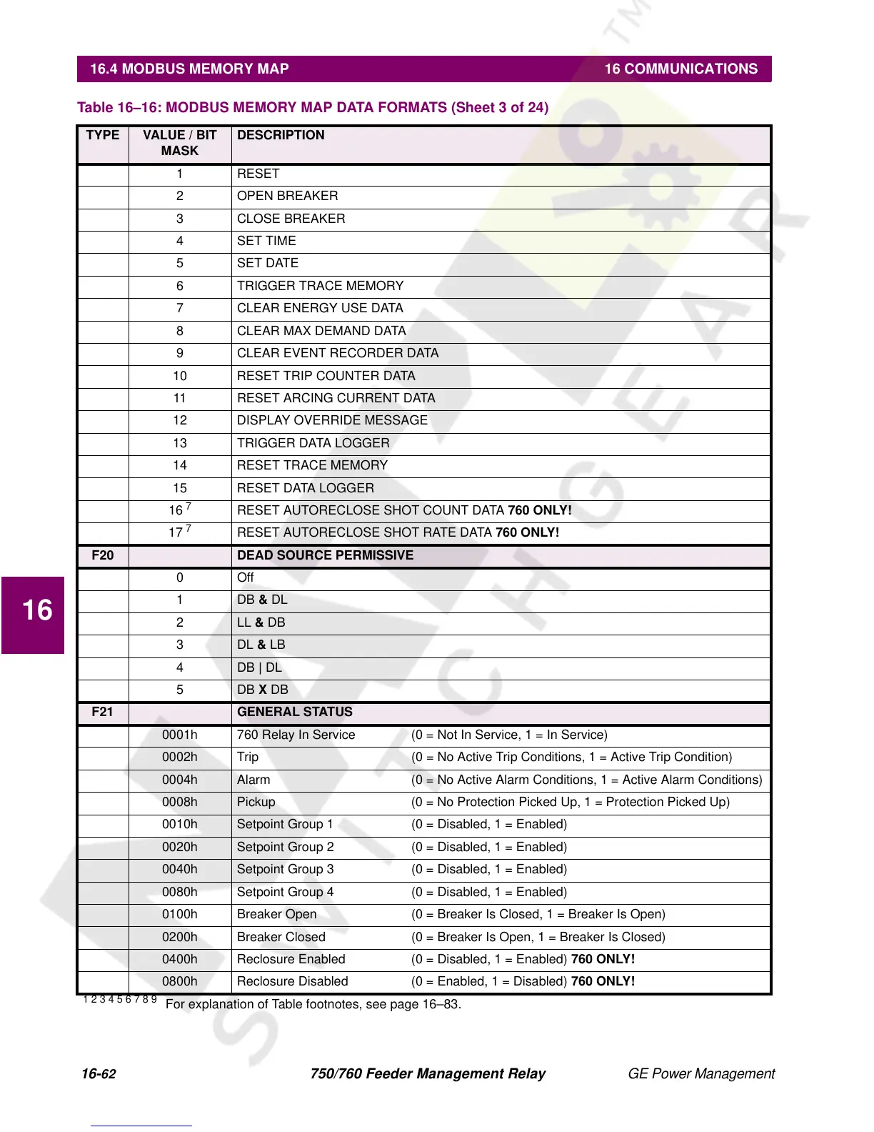
1 RESET
2 OPEN BREAKER
3 CLOSE BREAKER
4 SET TIME
5 SET DATE
6 TRIGGER TRACE MEMORY
7 CLEAR ENERGY USE DATA
8 CLEAR MAX DEMAND DATA
9 CLEAR EVENT RECORDER DATA
10 RESET TRIP COUNTER DATA
11 RESET ARCING CURRENT DATA
12 DISPLAY OVERRIDE MESSAGE
13 TRIGGER DATA LOGGER
14 RESET TRACE MEMORY
15 RESET DATA LOGGER
16
7
RESET AUTORECLOSE SHOT COUNT DATA
760 ONLY!
17
7
RESET AUTORECLOSE SHOT RATE DATA
760 ONLY!
F20 DEAD SOURCE PERMISSIVE
0Off
1DB
&
DL
2LL
&
DB
3DL
&
LB
4DB
|
DL
5DB
X
DB
F21 GENERAL STATUS
0001h 760 Relay In Service (0 = Not In Service, 1 = In Service)
0002h Trip (0 = No Active Trip Conditions, 1 = Active Trip Condition)
0004h Alarm (0 = No Active Alarm Conditions, 1 = Active Alarm Conditions)
0008h Pickup (0 = No Protection Picked Up, 1 = Protection Picked Up)
0010h Setpoint Group 1 (0 = Disabled, 1 = Enabled)
0020h Setpoint Group 2 (0 = Disabled, 1 = Enabled)
0040h Setpoint Group 3 (0 = Disabled, 1 = Enabled)
0080h Setpoint Group 4 (0 = Disabled, 1 = Enabled)
0100h Breaker Open (0 = Breaker Is Closed, 1 = Breaker Is Open)
0200h Breaker Closed (0 = Breaker Is Open, 1 = Breaker Is Closed)
0400h Reclosure Enabled (0 = Disabled, 1 = Enabled)
760 ONLY!
0800h Reclosure Disabled (0 = Enabled, 1 = Disabled)
760 ONLY!
Table 16–16: MODBUS MEMORY MAP DATA FORMATS (Sheet 3 of 24)
TYPE VALUE / BIT
MASK
DESCRIPTION
1 2 3 4 5 6 7 8 9
For explanation of Table footnotes, see page 16–83.

 Loading...


