16-
90
750/760 Feeder Management Relay GE Power Management
16.5 DNP 3.0 DEVICE PROFILE 16 COMMUNICATIONS
16
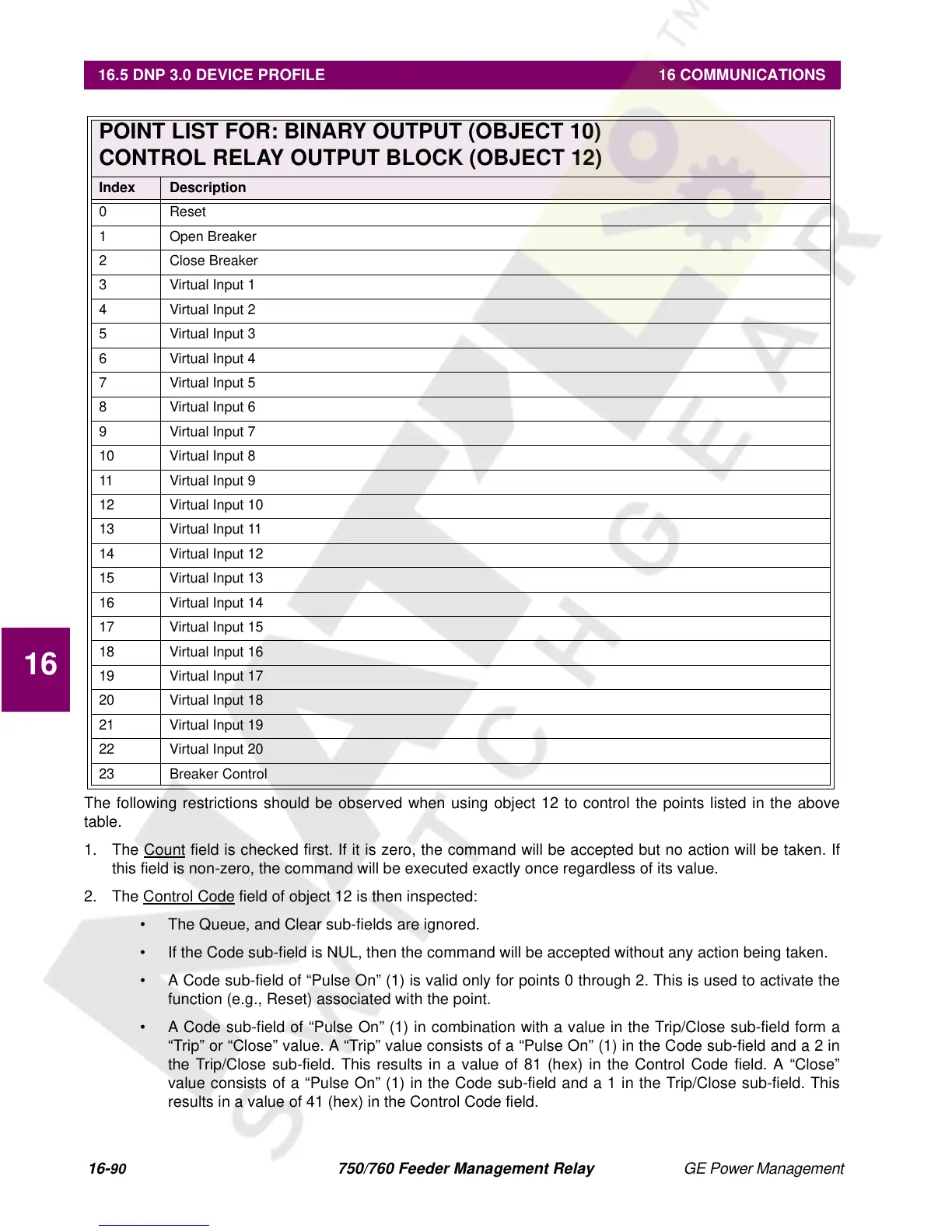
The following restrictions should be observed when using object 12 to control the points listed in the above
table.
1. The Count
field is checked first. If it is zero, the command will be accepted but no action will be taken. If
this field is non-zero, the command will be executed exactly once regardless of its value.
2. The Control Code
field of object 12 is then inspected:
• The Queue, and Clear sub-fields are ignored.
• If the Code sub-field is NUL, then the command will be accepted without any action being taken.
• A Code sub-field of “Pulse On” (1) is valid only for points 0 through 2. This is used to activate the
function (e.g., Reset) associated with the point.
• A Code sub-field of “Pulse On” (1) in combination with a value in the Trip/Close sub-field form a
“Trip” or “Close” value. A “Trip” value consists of a “Pulse On” (1) in the Code sub-field and a 2 in
the Trip/Close sub-field. This results in a value of 81 (hex) in the Control Code field. A “Close”
value consists of a “Pulse On” (1) in the Code sub-field and a 1 in the Trip/Close sub-field. This
results in a value of 41 (hex) in the Control Code field.
POINT LIST FOR: BINARY OUTPUT (OBJECT 10)
CONTROL RELAY OUTPUT BLOCK (OBJECT 12)
Index Description
0 Reset
1 Open Breaker
2 Close Breaker
3 Virtual Input 1
4 Virtual Input 2
5 Virtual Input 3
6 Virtual Input 4
7 Virtual Input 5
8 Virtual Input 6
9 Virtual Input 7
10 Virtual Input 8
11 Virtual Input 9
12 Virtual Input 10
13 Virtual Input 11
14 Virtual Input 12
15 Virtual Input 13
16 Virtual Input 14
17 Virtual Input 15
18 Virtual Input 16
19 Virtual Input 17
20 Virtual Input 18
21 Virtual Input 19
22 Virtual Input 20
23 Breaker Control

 Loading...


