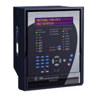
GE Power Management 750/760 Feeder Management Relay
vii
INDEX
S6 MONITORING....................................................... 13-1
S7 CONTROL ............................................................ 14-1
S8 TESTING.............................................................. 15-1
SAFETY PRECAUTIONS ........................................... 17-2
SAMPLE APPLICATION............................................... 2-5
SAVING SETPOINTS................................................... 4-9
SCHEME SETUP SETPOINTS ..................................14-31
SCR OUTPUT............................................................ 3-14
SELF-TEST WARNINGS ....................................... 5-5, 5-6
SENSITIVE GROUND CURRENT
measurement .........................................................17-12
sample application..................................................12-38
setpoints ................................................................12-30
SENSITIVE GROUND DIRECTIONAL OVERCURRENT
characteristics........................................................12-34
lo
ic dia
ram .........................................................12-36
protection scheme ..................................................17-32
setpoints ................................................................12-34
SENSITIVE GROUND INPUTS ..................................... 3-9
SENSITIVE GROUND INSTANTANEOUS OVERCURRENT
lo
ic dia
ram .........................................................12-33
protection scheme ..................................................17-31
setpoints ................................................................12-32
SENSITIVE GROUND TIME OVERCURRENT
lo
ic dia
ram .........................................................12-31
protection scheme ..................................................17-31
setpoints ................................................................12-30
SETPOINT ACCESS JUMPER
installin
................................................................... 2-3
pro
rammin
setpoints .............................................. 7-3
SETPOINT ACCESS SECURITY .................................. 7-3
SETPOINT CONTROL DIAGRAM ..............14-3, 14-4, 14-5
SETPOINT ENTRY METHODS ..................................... 7-2
SETPOINT GROUP CONTROL..................................17-51
SETPOINT GROUPS
for protection schemes ...........................................17-21
setpoints ................................................................. 14-1
SETPOINTS
1 trip and 2 close relay ............................................ 11-2
3-7 auxiliary relays .................................................. 11-5
access jumper ........................................................... 7-3
access security ......................................................... 7-3
analo
input rate of chan
e.....................................13-22
analo
input setup ..................................................13-18
analo
output .........................................................13-24
analo
outputs ........................................................ 15-4
analo
threshold.....................................................13-19
apparent power demand .........................................13-16
arcin
current.........................................................13-31
autoreclose ............................................................10-12
autoreclose current supervision...............................14-35
autoreclose rate supervision ...................................14-33
autoreclose zone coordination.................................14-36
block functions ........................................................ 10-7
block overcurrent functions ...................................... 10-9
breaker failure........................................................12-62
breaker functions..................................................... 10-4
breaker operation ...................................................13-33
bus undervolta
e....................................................12-49
bus VT sensin
.................................................. 9-2, 9-3
chan
in
................................................................... 2-3
clear data................................................................ 8-12
clock ......................................................................... 8-4
coil monitor ............................................................13-35
cold load pickup .....................................................14-11
common .................................................................... 7-4
control functions.......................................................10-5
current demand ......................................................13-10
current sensin
......................................................... 9-1
data lo
er................................................................ 8-7
default messa
es .....................................................8-10
DNP communications ................................................ 8-3
enterin
with software................................................ 4-8
entry methods ........................................................... 7-2
event recorder........................................................... 8-5
factory service........................................................15-10
fault values ..............................................................15-7
flexcurves ................................................................. 9-5
frequency decay.....................................................12-60
front panel ................................................................ 8-9
round directional...................................................12-27
round instantaneous overcurrent ...........................12-25
round time overcurrent..........................................12-23
installation ...............................................................8-13
installin
the setpoint access jumper .......................... 2-3
line undervolta
e....................................................12-52
loadin
from a file.....................................................4-10
manual close blockin
..............................................14-9
messa
e summary .................................................... 7-1
miscellaneous functions..........................................10-13
modbus....................................................................16-7
ne
ative sequence directional.................................12-45
ne
ative sequence instantaneous overcurrent .........12-43
ne
ative sequence time overcurrent ........................12-41
ne
ative sequence volta
e .....................................12-47
neutral current..........................................................13-1
neutral directional...................................................12-20
neutral displacement ..............................................12-56
neutral instantaneous overcurrent ...........................12-18
neutral overcurrent .................................................12-16
neutral time overcurrent..........................................12-16
numerical .................................................................. 2-3
output relays ............................................................15-1
overfrequency ........................................................13-27
overvolta
e ............................................................12-54
passcode .................................................................. 8-1
phase current ...........................................................13-1
phase directional ....................................................12-13
phase instantaneous overcurrent ............................12-11
phase time overcurrent .............................................12-7
pickup test ...............................................................15-2
port setup ................................................................. 8-2
postfault values ........................................................15-9
power factor .............................................................13-4
power system ............................................................ 9-4
prefault values .........................................................15-7
pulse output ...........................................................13-39
reactive power demand...........................................13-14
readin
lo
ic dia
rams............................................... 7-6
real power demand .................................................13-12
reclosure shots.......................................................14-37
restricted earth fault ...............................................12-37
savin
to a file........................................................... 4-9
scheme setup.........................................................14-31
sensitive
round current .........................................12-30
sensitive
round directional ....................................12-34
senstive
round instantaneous overcurrent..............12-32
senstive
round time overcurrent ............................12-30
setpoint
roups ........................................................14-1
simulation ................................................................15-5

 Loading...