Q-10 Series 90™-30 PLC LONWORKS® Bus Interface Module User's Manual
–
June 1997 GFK-1322A
Q
3
.
Using a L
ON
W
ORKS
network installation tool, install the module in the network and bind the
variables.
This step binds the individual variables from the network into the type slots defined
previously. When these variables are updated, the new values are passed into the proper PLC
register locations. When the PLC updates a register value , the new value is transferred to the
network.
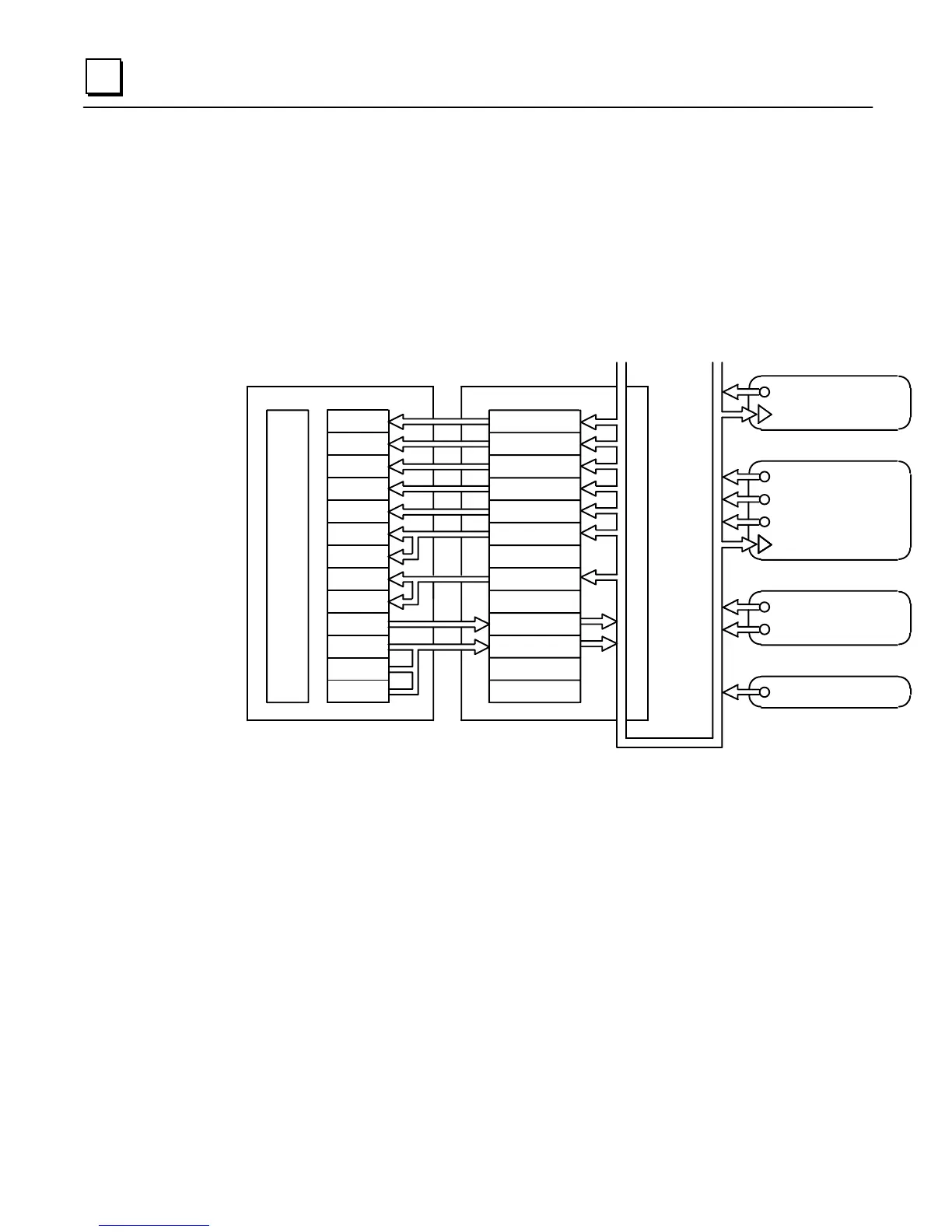
Example: In the example illustrated in Figure Q-4, a change in the value of the input on Node 4
will cause its network variable to update on the network. This value is acquired in the LBIM and
forwarded to registers 6 and 7 in the PLC.
NVO_7, SNVT_temp_f
NVO_1
SNVT_count
NVI_1, displa
Node 1
NVO_1, SNVT_temp
NVO_3, SNVT_temp
NVO_4, SNVT_fre
_f
NVI_2, SNVT_temp
NVO_5, SNVT_count
NVO_6, SNVT_temp
Node 2
Node 4
Node 3
CPU
Re
1
Re
2
Re
3
Re
4
Re
5
Re
6
Re
7
Re
8
Re
9
Re
10
Re
11
Re
12
Re
13
PLC LonWorks BIM
nvi_1
nvi_2
nvi_4
nvo_2
nvi_7
nvi_3
nvi_6
nvi_3
nvo_2
LonWorks Network
Figure Q-4. Example: Installing the Module in the Network and Binding the Variables

 Loading...


