EasyManua.ls Logo

GE af-600 fp - User Manual

GE af-600 fp
175 pages
Print Icon
To Next Page IconTo Next Page
Loading...
GE Consumer & Industrial
Electrical Distribution
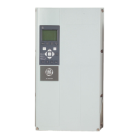
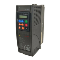
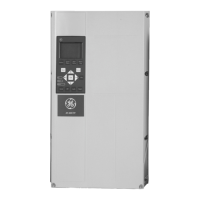
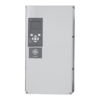
AF-600 FP
TM
Fan and Pump Drive
(460V/575V 150HP and above)
Operating Instructions
The instructions do not purport to cover all details or variations in equipment nor to provide for every possible
contingency to be met in connection with installation, operation or maintenance. Should further information be
desired or should particular problems arise which are not covered sufficiently for the purchaser’s purposes, the
matter should be referred to the GE company.
AF-600 FP is a trademark of the General Electric Company.
GE Consumer & Industrial
41 Woodford Avenue
Plainville, CT 06062
www.geelectrical.com/drives
130R0135 MG11U102
*MG11U102*
DET-610

Table of Contents

Other manuals for GE af-600 fp

Questions and Answers

  • G
    Gary PenaSep 8, 2025
    Why is my GE DC Drives motor not running?
    • M
      Ms. Jamie AndersonSep 8, 2025
      Several factors can prevent your GE DC Drives motor from running. Here's what to check: * Ensure the service switch is closed and the motor connection is secure. * If using a 24V DC option card, verify mains power is applied. * If the keypad stop is active, press [Auto] or [Hand], depending on your operation mode. * Confirm a valid start signal is applied. * Check if the motor coast signal is active; if so, apply 24V to the terminal or program it to No operation. * Verify that the reference signal source is correctly programmed, check the wiring, scaling of terminals and reference signal.
  • I
    ievansSep 7, 2025
    What to do if GE af-600 fp DC Drives power fuses open or circuit breaker trips?
    • M
      melinda93Sep 7, 2025
      If the power fuses open or the circuit breaker trips in your GE DC Drives, it could be due to several reasons. First, check for any phase-to-phase shorts and eliminate them. Second, the motor might be overloaded; perform a startup test to verify the motor current is within specifications. If the motor current exceeds the nameplate full load current, reduce the load. Finally, ensure all connections are tightened, as loose connections can also cause this issue.
  • B
    Bradley AndersonAug 22, 2025
    How to fix a dark display or no function on a GE Controller?
    • G
      garciatimothyAug 22, 2025
      If the display is dark or has no function on your GE Controller, first check the input power source. Then, inspect for any missing or open fuses, or a tripped circuit breaker, following the provided recommendations. Also, check if there's power to the keypad; if not, replace the faulty keypad or connection cable. Ensure the terminals are wired properly to avoid a shortcut on the control voltage. Finally, adjust the contrast by pressing [Status] + [?]/[?]. If the issue persists, the display (keypad) may be defective and require replacement. For an internal voltage supply fault or a defective SMPS, it is recommended to contact the supplier.
  • D
    Dylan StephensSep 4, 2025
    What to do if the motor will not brake on my GE Controller?
    • L
      Lauren MaySep 4, 2025
      If the motor will not brake on your GE Controller, it's possible that there are incorrect settings in the brake parameters or the ramp-down times are too short. Check parameter group B-0# DC brake and F-5# Extended Reference.
  • C
    Christopher MataSep 3, 2025
    What causes a GE Controller motor to run rough?
    • J
      jacqueline76Sep 3, 2025
      If the motor runs rough on your GE Controller, it might be due to over-magnetization. Check the motor settings in parameter groups P-0# Motor Data, P-3# Adv Motor Data, and H-5# Load Indep. Setting.
  • P
    Paul BurgessSep 2, 2025
    Why is the motor speed unstable on my GE Controller?
    • V
      Victoria LopezSep 2, 2025
      If the motor speed is unstable on your GE Controller, it may be due to incorrect parameter settings. Check the settings in parameter group AN-##. For closed-loop operation, check settings in parameter group CL-0#.
  • R
    Rachel ClaytonAug 31, 2025
    How to increase motor speed on GE Controller?
    • C
      Carol RodriguezAug 31, 2025
      If the motor on your GE Controller is not reaching maximum speed, the frequency limits may be set incorrectly, or the reference input signal may not be scaled correctly. To resolve this, program the correct limits and settings.
  • T
    Travis SteeleAug 30, 2025
    Why does the GE Controller have open power fuses or a tripped circuit breaker?
    • J
      Jacqueline GravesAug 30, 2025
      If your GE Controller experiences open power fuses or a tripped circuit breaker, it could be due to a phase-to-phase short, motor overload, or loose connections. Eliminate any shorts that are detected. Perform a start-up test to verify the motor current is within specifications; if it exceeds the nameplate full load current, the motor may need to run with a reduced load, and you should review the application specifications. Ensure that all connections are tightened.
  • A
    Amber OsborneAug 29, 2025
    What to do if motor current imbalance on GE Controller?
    • B
      bridgesbobbyAug 29, 2025
      If the motor current imbalance is greater than 3% on your GE Controller, the problem might be with the motor or its wiring. Try rotating the output motor leads one position: U to V, V to W, W to U. Alternatively, the issue could be with the adjustable frequency drives themselves, and rotating the output motor leads as described can help.
  • R
    Ryan MillsAug 27, 2025
    Why is my GE Controller motor running in the wrong direction?
    • J
      Jeremy RomeroAug 27, 2025
      If your GE Controller's motor is running in the wrong direction, the cause may be related to the motor rotation limit, an active reversing signal, or incorrect motor phase connection. Program the correct settings to adjust the motor rotation limit. Deactivate any active reversing signals. Refer to section 3.5 in this manual to check the motor rotation.

Summary

How to Read these Operating Instructions

Copyright, Limitation of Liability and Revision Rights

Details proprietary information, warranty limitations, and revision rights for the manual.

Symbols and Available Literature

Explains symbols used in the manual and lists related literature for further information.

Safety

High Voltage and General Warnings

Covers high voltage hazards and general safety warnings for equipment operation.

Safety Instructions and Precautions

Provides essential safety instructions for installation and operation.

Before Commencing Repair Work

Outlines mandatory steps before performing any repair or maintenance.

Installation Considerations

Addresses special conditions like high altitudes, IT mains, and environmental factors.

Disposal Instruction

Provides guidance on the proper disposal of electrical and electronic waste.

Electrical Installation

Power Connections and Cabling

Details requirements for power cable connections, including sizing and fusing.

Earthing and Shielding

Explains earthing requirements for EMC and shielding practices for noise reduction.

Protection (Fuses, RCD, Overload)

Covers protection against overcurrent, RCD usage, and electronic overload settings.

Motor Cable and Connections

Details motor cable selection, connection, and length considerations.

Load Sharing and Noise Shielding

Explains load sharing for multiple converters and EMC shielding.

Mains and Fan Supply Connections

Covers mains connection requirements and external fan supply options.

Fuses and Tables

Provides detailed fuse tables for various unit sizes and ratings.

Motor Insulation and Bearing Currents

Discusses motor insulation requirements and mitigation of bearing currents.

Control Cable Routing and Terminals

Details routing of control cables and access to control terminals.

Connection Examples

Illustrates common connection examples like start/stop and potentiometer reference.

Switches and Configuration

Explains the function of DIP switches S201, S202, and S801 for configuration.

Final Set-up and Test

Guides through the process of setting up and testing the frequency converter.

Additional Connections

Covers parallel motor connections and motor thermal protection.

Introduction

Frequency Converter Identification

Details how to identify the frequency converter using its nameplate.

Model Numbering System and Abbreviations

Explains the model numbering system and provides a list of abbreviations.

Mechanical Installation

Getting Started and Pre-installation

Covers initial steps for installation and site planning.

Transportation, Unpacking, and Lifting

Provides instructions for safely handling and moving the unit.

Mechanical Dimensions

Details the physical dimensions of different unit sizes.

Tools and General Considerations

Lists required tools and general considerations for installation space.

Terminal Locations

Shows terminal positions for various unit sizes to aid cable routing.

Cooling and Airflow

Explains cooling methods and required airflow for heat dissipation.

Installation Procedures (Wall, Gland, Drip Shield)

Details wall mounting, gland entry, and drip shield installation.

Field Installation of Options

Describes installation of optional kits like duct cooling.

Installation on Pedestal

Provides instructions for mounting the unit on a pedestal.

Mains Shield and Panel Options

Covers installation of mains shields and panel options.

How to operate the frequency converter

Keypad Operation Overview

Introduces the keypad structure and operating methods.

Keypad Navigation and Buttons

Explains the function of navigation keys and operation buttons.

Communication and PC Connection

Details RS-485 bus connection and PC connection via USB.

PC Software Tools

Describes the Drive Control Tool DCT 10 for parameter management.

Tips and Tricks

Offers helpful tips for efficient operation and parameter setup.

Parameter Settings Transfer and Restore

Guides on transferring and restoring parameter settings.

How to Program

Parameter Groups Overview

Lists and describes the main parameter groups for programming.

Quick Menu Mode and Setup

Explains using the Quick Menu for efficient setup and parameter access.

Motor Data Configuration

Details parameters for entering motor specifications for optimal performance.

Speed and Time Settings

Covers configuration of speed limits, acceleration, and deceleration times.

Macros Configuration

Explains using Macros for quick access to application-specific parameters.

Analog Input;Output Configuration

Details configuration of analog inputs and outputs for control signals.

HVAC Application Parameters

Covers parameters specific to HVAC applications like pumps and fans.

PID Closed Loop Configuration

Explains how to configure the PID controller for closed-loop operations.

Pump Controller Configuration

Details parameters for the built-in pump cascade controller.

Logic Controller Configuration

Describes parameters for the built-in Logic Controller for custom sequences.

Braking Functions

Covers configuration of braking functions like DC hold and over-voltage control.

General Specifications

Electrical and Environmental Specs

Provides electrical ratings, supply details, and environmental requirements.

Torque and Cable Specifications

Details torque requirements and cable length/cross-section limits.

Input;Output Terminal Specs

Specifies characteristics of digital, analog, and relay I/O terminals.

Control Characteristics

Outlines control characteristics like response time and speed accuracy.

Performance Tables

Presents detailed performance data across various models and mains supplies.

Warnings and Alarms

Fault Message Overview

Explains how warnings and alarms are indicated and how to reset them.

LED Indicators and Status Words

Describes LED indications and alarm/warning status word meanings.

Common Fault Messages

Lists common faults with their descriptions and potential causes.

Specific Fault Code Details

Provides detailed explanations for specific alarm and warning codes.

GE af-600 fp Specifications

General IconGeneral
BrandGE
Modelaf-600 fp
CategoryDC Drives
LanguageEnglish

Related product manuals