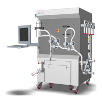
Components on system — inlet
s
ide
The illustration below shows the location of components on the inlet side of ÄKTA
ready XL. The system is shown without the flow kit.
Part Component ID tag Function
1 Air trap vent
v
alve
XV-023 A valve controlling the level in air trap.
2 Connectors - Connection points for the system, see Lo-
cation of connectors, on page 42.
3 Power
switch
- The system mains power switch, located
on the inlet side (left side) of the system.
4 Reset button - The Reset button must be pressed after
the system has been stopped for an emer-
gency, after rectifying an alarm, and at each
change of valve positions to the Run posi-
tion using the installation switch.
3 System description
3
.2 Illustrations
34
ÄKTA ready XL Operating Instructions 29281616 AE
*** TeDIS Valid on Date Printed Printed on: 15-09-2023 11:27:35 ***

 Loading...