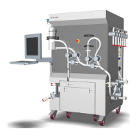
Part Component ID tag Function
5 Installation
s
witch
- The switch is used for releasing and engag-
ing valves during flow kit and column instal-
lation. The switch has three different posi-
tions:
Flow kit install: : This mode opens all
valves. The user can then manually open/
close valve locks.
Run: : This mode engages all valves. The
user cannot open the safety valve locks —
the valves are controlled by the system.
Drain: This mode opens and closes valves
in a specific order to allow for removal of
liquid from tubing and pumps via the col-
umn bottom connection.
6 Cable for
c
onnection
to air sensor
AE-151 A cable for air sensor AE-151 communica-
tion cord.
7 Inlet valves XV-011
t
o
XV-014
Four inlet valves, located on the inlet side
(left side) of the system for pump B.
8 Inlet valves XV-001
to
XV-006
Six inlet valves, located on the inlet side
(left side) of the system for pump A.
9 Caster wheel
(4 pcs)
- Four caster wheels with wheel brakes.
10 Cable for
connection
to conductiv-
ity and tem-
perature sen-
sor
CE-101/
TE-101
A cable for communication to conductivity
and temperature sensor CE-101/TE-101
fitted on the flow kit.
11 Operator
console
- The system is equipped with a monitor
screen and keyboard for convenient user
access (only applicable to system with
UNICORN control software).
3 System description
3
.2 Illustrations
ÄKTA ready XL Operating Instructions 29281616 AE 35
*** TeDIS Valid on Date Printed Printed on: 15-09-2023 11:27:35 ***

 Loading...