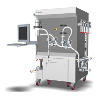
Overview
Valves Description Default posi-
t
ion
XV-001 to
XV-006
Inlet A valves, located on the left-hand side
of the system.
Closed
XV-011 to
XV-014
Inlet B valves, located on the left-hand side
of the system
Closed
XV-021 to
XV-022 and
XV-024
Air trap valves, located on the front of the
system
Inline
XV-023 Air trap vent valve, located on the top left-
hand side of the system
Closed
XV-025 to
XV-027
Filter valves, located on the front of the sys-
tem
Bypass
XV-031 to
XV-035
Column valves, located on the right-hand
side of the system
Bypass
XV-051 to
XV-056
Outlet valves, located on the right-hand
side of the system
Closed
Refer to the Software Design Specification for more options and details.
Air trap valves
The air trap valve blocks are directly connected, either to the optional filter valve
blocks or to tubing going to the air sensor prior to the column. See the valve macros
for the air trap instruction options below.
Valve positions Open valves
Bypass XV-022
Inline
(default) XV-021 + XV-024
Fill XV-021 + XV-023
Fill_Inline XV-021 + XV-023 + XV-024
3 System description
3
.4 System components
3.4.4 Valves
58
ÄKTA ready XL Operating Instructions 29281616 AE
*** TeDIS Valid on Date Printed Printed on: 15-09-2023 11:27:35 ***

 Loading...